Escher Code Generator
Creative Commons
August 2005
Abstract
This guide is the primary reference document for the engineers and scientists translating Nucleus BridgePoint® xtUML models with the MC-3020 model compiler. It explains how to use the compiler's features and capabilities.
Table of Contents
- 1. Users Guide
- 2. Features and Components
- Features
- Multi-Pass Corroborative Translation
- Multi-Tasking/Threading
- Prioritization
- Multi-Domain Support
- Persistence
- Metrics and Reporting
- Bridge/Operation Skeleton Generation
- ``Call Outs'' for User Code
- UDT Precision and Pointer Types
- Attribute Bit Fields
- Selection Optimization
- Interrupt Handler Bridging
- User Defined Archetypes
- ANSI C Purity and Simplicity
- Preexisting Instances Defined in Data
- xtUML Model Debugger
- Components
- Restrictions and Limitations
- 3. EDGE (Eclipse) Integration
- 4. Marking
- 5. Translation and Build
- 6. Enumerated Types
- 7. Interface Call-outs
- 8. Initialization and Preexisting Instances
- 9. MC-3020 Collections
- 10. Model Debugger
- 11. Persistence
- 12. Tasking/Threading
- A. Deployment
- B. Quick Start
- C. Analysis Guide
- D. Background
- E. PEI Test Case Setup
- F. Legal Notice
List of Figures
- 8.1. Autosampler Class Diagram
- 8.2. Autosampler Init Function
- 8.3. Model Debugger Architecture
- 8.4. PEI Test Case Class Diagram
- 8.5. MD System Browser for PEI Test Case
- 8.6. MD PEI Test Case Initializing
- 8.7. Experiment Class Diagram
- 8.8. MD System Browser for exp and as2
- 8.9. MD Initializing Autosampler
- 8.10. MD Initializing Experiment
- 9.1. Singly Linked Lists of Instances
- 9.2. Doubly Linked Lists of Instances
- 9.3. Parallel Container/Object Arrays
- 9.4. Containers Merged Into Instance Data
- 10.1. Model Debugger Architecture
- 10.2. Current Debugger/Compiler Interface
- 10.3. Near Term Debugger/Compiler Interface
- 11.1. Persistence Analysis Domain Chart
- 11.2. Persistence Class Diagram
- 11.3. Non-Volatile Storage Class Diagram
- D.1. Model Compiler Analogy with Nucleus BridgePoint Tool Set
- E.1. PEI Model Init Function
List of Tables
- 8.1. PEI Comparison
List of Examples
- 4.1. Example of xtUML Domain Registration
- 4.2. Example of Realized Domain Registration
- 4.3. Wiring Between xtUML Domains
- 4.4. Wiring Between xtUML Domains Using Bridge Object
- 4.5. Wiring a Realized Domain
- 4.6. Tagging Interrupt Bridges
- 4.7. Data Type Precision
- 4.8. Mapping Pointer Types
- 4.9. Specifying a Value for the Default Uninitialized Enumerator
- 4.10. Specifying Enumerator Values
- 4.11. Enabling Tasking/Threading
- 4.12. Setting Task/Thread Priority
- 4.13. Defining String Length
- 4.14. Max Relationship Extent
- 4.15. Max Selections Extent
- 4.16. Collection Node Type Selection
- 4.17. Self-Directed Queue Depth
- 4.18. Instance Directed Queue Depth
- 4.19. Pending xtUML Timers
- 4.20. Interleaved Bridges Queue Depth
- 4.21. Interleaved Bridge Argument Data
- 4.22. Enabling Model Debug Code
- 4.23. Changing Persistence Cache Queue Depth
- 4.24. Tagging Initialization Functions
- 4.25. Tagging Excluded Classes
- 4.26. Tagging Excluded Subsystems
- 4.27. Not Translating a Function
- 4.28. Enabling State Transition Tracing
- 4.29. Enabling Action Language Tracing
- 4.30. Enabling Empty Reference Usage Detection
- 4.31. Forcing Generation Non-Optimal Code
- 4.32. Mapping Classes to Tasks
- 4.33. Tagging Max Instances
- 4.34. Tagging Default Extent
- 4.35. Marking Classes as Having PEIs Defined in Data
- 4.36. Marking Classes with Static Instance Populations
- 4.37. Marking Read-Only Classes
- 4.38. Marking (Non-) Persistent Classes
- 4.39. Not Translating Operations
- 4.40. Tagging a Priority Event
- 5.1. Simple rox_build Example
- 5.2. Two Domain rox_build Example
- 7.1. Bring-up Initialization
- 7.2. Pre-xtUML Initialization
- 7.3. Post-xtUML Initialization
- 7.4. Background Processing
- 7.5. Pre-Shutdown
- 7.6. Post-Shutdown Callout
- 7.7. Event Can't Happen
- 7.8. Event with No Instance
- 7.9. Event Free List Empty Handler
- 7.10. User Empty Handle Detection
- 7.11. Object Pool Empty
- 7.12. Node List Empty
- 7.13. Overflow of Interleaved Bridge
- 7.14. Event Queue Empty Notification
This chapter describes the purpose and use of this guide, lists other related documents, and presents the conventions used within.
This section explains the intent of this document and describes its usage.
The purpose of this guide is to enable the user of the MC-3020 model compiler to generate and execute an ANSI C program from Shlaer-Mellor xtUML models specified in the Nucleus BridgePoint Model Builder. Essential tasks that this guide will enable the user to perform include the following.
Install MC-3020.
Translate xtUML models into ANSI C code.
Build an executable program.
Create xtUML models that fully utilize the capabilities of MC-3020.
This guide is written for software engineers who are using the Shlaer-Mellor development method and will implement their system using the MC-3020 model compiler. It assumes that the user is familiar with the ANSI C programming language and general usage of the development platform and its software development utilities.
There are various roles that software engineers can play in the course of developing a system. These roles reflect the different types of tasks that must be undertaken to successfully specify, design, construct, and test a system. Roles that are relevant to the usage of the MC-3020 model compiler include the following.
| Analyst | Develops the xtUML models on the Nucleus BridgePoint tool set that specify system behavior and that will be used to construct the final system. |
| Software Architect | Installs and maintains the MC-3020 Model Compiler. Frequently assists in its use to translate the xtUML models and build the system. |
| System Architect | Makes system wide decisions about how the xtUML models will be ``marked'' to utilize the facilities provided by MC-3020. This person frequently assists in the translation and building of the system. |
| Programmer | Designs and develops C or other code that interfaces to the MC-3020 generated code. |
| Tester | Tests the system. |
An engineer in each of these roles will be looking for different types of information in this guide to fulfill the tasks of that role.
The Analyst will want to understand how to use MC-3020 modeling conventions to specify such things as instance initialization and bridge operations. The Analyst will also be interested in understanding the limitations that MC-3020 places on the xtUML models.
The Software Architect will want to understand how to install and run MC-3020 as well as understand its structure well enough to maintain it.
The System Architect will want to understand the underlying software design or architecture provided by MC-3020 and the marking options that are available for translating the xtUML models into ANSI C code.
The Programmer will want to understand the published interfaces to the MC-3020 generated system and how to use them to successfully interact with the generated components.
The Tester will want to understand how to execute and debug the generated system for ``black box'' testing, and how the system is constructed and operates for ``white box'' testing.
The following section provides guidance on using this guide to meet these needs.
This section describes the general structure of this guide and provides suggestions for its usage in different situations.
The guide is assembled with the more frequently accessed chapters toward the front. These chapters are in roughly chronological order according to how they will be used. General Shlaer-Mellor development background is provided toward the end.
Here is a short description of each chapter and appendix.
Appendices have been provided.
This chapter provides a concise overview of many of the capabilities built into MC-3020. The basic gist of translation strategy for model components is given in an outline format.
MC-3020 delivers translation technology and a set of features and components found in no other model compiler existing to date. The mix of optimizations, conveniences and simplicity provide a solid foundation upon which ``down on the iron'' embedded designs can be based.
The translation engine embodied in the MC-3020 Model Compiler performs two passes across the xtUML model under translation. The first pass analyzes the model structure and action language semantics of each domain. The results of this analysis drive the generation in the second pass. The second pass generates code and data that is minimized and optimized for speed. Unaccessed data and unneeded code are eliminated.
This multi-pass intelligence spans domains and allows for optimizations at the system level based on information collected and collated from all domains in the system.
Preemptive multi-tasking is supported on the Nucleus PLUS® real-time operation system (RTOS) and on systems supporting POSIX threading. Single-task operation (with or without and RTOS) is also supported. Tasking supplies a rich means of providing preemptive prioritization among the xtUML classes running in the system.
Preemptive task/thread prioritization is provided in the generated C code. Groups of xtUML classes are mapped to tasks running at differing priorities.
MC-3020 also provides for prioritization through the marking of events. Higher priority xtUML threads of control can run without being preempted by lower priority activities.
MC-3020 cleanly translates large systems consisting of multiple xtUML and realized domains. Support is provided to integrate and interface to hand-craft, legacy and/or off-the-shelf code.
MC-3020 supports the marking of persistent classes. The instance data for classes marked as persistent is restored at power-up from a non-volatile storage (NVS) device.
A set of metrics is generated and reported each time the model compiler is run. Statistics on classes, associations, events and first pass analysis results are stored in a report directory.
Metrics provided can be fed back to the analyst to provide a focus on recognized dangerous practices and fully illegal operations and accesses. Some of the metrics relate to sizing and complexity. These metrics could easily be tracked over the life of a project to provide quality and effort related measurements.
Based upon information modeled in Nucleus BridgePoint Model Builder MC-3020 automatically generates source code frameworks for operations and outbound bridge implementation. These skeleton files will actually compile as generated. The user is saved from delving into generated code to divine interfaces required for these boundary functions. Kind and helpful comments are provided to guide insertion of bridge and operation implementation code.
Support is provided for translation of AL in operation and bridge descriptions. The same action language used for Nucleus BridgePoint Model Verifier is translated into the of bodies of the operation C source files and the bridge skeleton files.
Several hooks have been supplied to allow easy interfacing of user supplied code to the system level generated code. A source module is automatically generated that supplies empty functions which are invoked at various points during initialization, dispatch processing and shut down. These empty functions can be populated with user code for ``can't happen'' events, hardware bring-up, ``background'' processing, legacy clean-up and more.
To allow optimization for space and control over precision, the storage classes of integer and real based user-defined data types (UDTs) can be supplied by the user. MC-3020 also allows user-defined data types to be implemented as pointers. The pointer types are very convenient for passing across bridges (in both directions). Precision and pointer information is provided to the model compiler through marking.
Further optimization of space is provided through ANSI C bit field support. Multiple attributes can be packed into a single word of storage. This feature may also be used (with caution) in conjunction with memory mapped classes to model hardware with xtUML constructs.
MC-3020 attempts to optimize select any [inst_ref] from instances of [key_letters] where [where clause] when the where clause is checking for equality of the identifier. MC-3020 optimizes for code space. In addition, hooks into the scanning routines are provided to enable customizations to the selection search algorithms. Applications dealing with large collections of class instance data (hundreds or thousands) may use these hooks to further speed the selection process.
MC-3020 provides a safe way to bridge into the application from interrupt handlers (or other external tasks). Consistency is maintained in software architecture data structures and application data access sets.
A means is provided for the user to supply application specific fule file functions. This capability serves to extend the marking capabilities of MC-3020. It is possible to steer code generation in such a way as to provide customizations characteristic of particular target platforms, compilers and tool sets.
MC-3020 is purely ANSI C and generates code that can be compiled by any compiler compliant with the ANSI standard. The core model compiler uses no libraries or system functions. stdio.h is included simply for convenience during debug (for printf, etc). All generated code is simple, native C.
As of version 3.1, MC-3020 supports initialization of preexisting instances in data. This provides a substantial optimization in both bring-up execution speed and overall code footprint. Instead of creating, relating and initializing all of the classes at start-up, pre-existing class instances can be pre-populated with static initializers. Support is maintained for dynamic initialization using an initialization function (or an initialization object).
As of version 3.1, MC-3020 supports xtUML-level model debugging with Nucleus BridgePoint Model Debugger. This support allows execution tracing at state action as well as the AL statement level. The state of the system can be openly queried and viewed at any point of execution. Support is limited to execution on the host computer or socket-capable targets with sufficient RAM capacity.
MC-3020 is a modular software architecture characterized by a distinct effort to maximize component independence. The coupling between the model compiler components has been minimized while maximizing component cohesion. A model of the architecture drives the implementation of the generation components.
To a great extent components can be modified independently. Additional components can be added. This makes MC-3020 ideal for extension and modification. In a limited fashion, individual architecture components can be ``unplugged'' and new or modified components ``plugged in'' to replace them. For example, the strategy for collecting instances can be changed by modifying or replacing only the localized component. Names and coding style rules are concentrated into a single component allowing architects to dial in a preferred naming convention and generation style.
Each class is translated into an ANSI C structure. Instances are maintained in collections of instances of classes (class extents). Space for class instances is pre-allocated at bring-up time.
Creation occurs in constant time. Creation can occur synchronously with the create action language statement or asynchronously with a creation event. In synchronous creation, no action is executed. In asynchronous creation, a creation state is executed and at minimum initializes the instance identifier.
Instance deletion moves an class instance from the active extent and deactivates it onto a list of inactive (``inanimate'') class instances. If no action language ever performs deletion of a particular class, no deletion accessor method is generated.
Instance selection is optimized for speed when selecting based on the instance identifier. For unoptimized selections O(N) (linear) time is required. (MC-3020 provides O(N) for all ``blind selections'', select any from instances of action language commands.) Hooks are provided for architect replacement of certain signature selection search functions.
Attributes are elements of the translated structure. Most attributes are translated with no function interface layer. No call/return overhead is incurred for most attribute read and write operations. Code is generated to directly access attribute data. Speed is optimized.
In typical models, some attributes are never accessed. MC-3020 detects this situation and omits the implementation of attribute data elements that are never accessed. Unused data is optimized away.
Associations are optimized by storing a copy of the instance handle as extended attribute data. This optimization is implemented between sub/super-types as well.
As with data attribute elements, MC-3020 optimizes away unused referential attributes. Relate, unrelate (link and unlink) and association traversal operations are optimized for low overhead. These operations are performed directly on instance data when appropriate avoiding the generation and associated run time overhead of function calls.
The translated state models are optimized for speed. State transitions and action dispatches execute in constant time. The state event matrix is implemented as a two dimensional array. Rows represent states; columns are indexed by event to obtain the transition.
Actions are translated into functions associated by name and packaging with the class containing the state model containing the state action.
Adherence to Shlaer-Mellor event rules is assured in the generated code. Centralized event queues order events for the entire system.
Prioritized events can be marked by the user. 256 priority levels are provided.
Creation events are recognized and treated differently from non-creation events. The model compiler will create an instance of the class before the event is delivered. The event will cause a transition into the creation state and execution of the associated action.
Domain functions (bridges) and operations are listed together, because MC-3020 treats them with a great deal of symmetry. Domain functions and operations translate into C function invocations. Any number of arguments can be passed.
Domain functions (synchronous services) are supported between domains. Events across bridges are not allowed.
MC-3020 generates bridge and operation frameworks. These frameworks provide the entire invocation interface. A comment is provided to guide the user in where to insert implementation code. These skeletons will compile with or without inserted user code. However, the bridge must be declared to the generation system and the bridge must be wired. See Chapter 4, Marking for details on how to accomplish this.
These are the unclassified features.
Marking allows Nucleus BridgePoint Model Verifier flavored initialization objects to be used for system initialization. In addition, several initialization objects can be defined in the model and only one marked to generate code.
Various stylistic and implementation conventions are centralized and documented to be easily controlled by the software architect. Generated file names, directory structure, coding conventions and even coding style can be dialed in by the user. (Look for fule files with the word ``name'' in the file name.)
See release notes for most recent restrictions and limitations.
No dynamic memory allocation. System storage space for all instances is pre-allocated at start-up. This implies marking the OIM to define the maximum number of instances needed for each class. Note that MC-3020 intelligently determines rational defaults for instance and event populations. Sophisticated analysis is performed to size instance, event and queue populations across multiple domains. Marking is used to dial these in tightly.
Some platforms have no real time clock. Therefore date and time may not be available in standard Gregorian or Caesarian form.
State machines are optimized for speed rather than space.
Events across bridges are not allowed.
Navigations of composed associations must explicitly use the ``real'' (non-composed) association formalizations.
Association conditionality is not enforced by the model compiler.
Actions may not leave identifying attributes inconsistent beyond the end of any action.
MC-3020 attempts to optimize select any [inst_ref] from instances of [key_letters] where [where clause] for code size when the where clause is checking for equality of the identifier. Future versions of MC-3020 may provide advanced (hashed) searching techniques to optimize the blind selections for speed. In MC-3020, certain limitations apply to the selection optimization when unnecessary parentheses are used in the where clause expression. To guarantee the best optimization, avoid unnecessary parentheses in where clauses.
Blind selections following a create and in the same scope as the create may not see the newly created instance in the extent.
create object instance of keyletters (create with no return value) is allowed only when the identifier of class keyletters is of type unique_ID.
The implementation of string expressions is somewhat inelegant. Strings in expressions are limited to simple binary operations.
There is no support for ``N to N + 1'' release compatibility. Changes to a model result in changes in the code, including event numbers, state numbers, etc. The registration theme is introduced to pave the way for future N+1 release capability.
The MC-3020 build process has been integrated with Nucleus BridgePoint Model Debugger version 7 and Nucleus EDGE, the Embedded Developers Graphical Environment. EDGE is based upon the Eclipse framework. The use of MC-3020 in this environment is described in this section.
MC-3020 can now be run from inside of Nucleus BridgePoint Model Builder/EDGE. Nucleus BridgePoint Model Builder version 7 now runs within an Eclipse environment. This environment provides excellent flexibility to integrate tools together. Eclipse is open and easy to modify. EDGE is the name of the Eclipse environment as customized for xtUML and embedded development.
Read the user guides for Nucleus BridgePoint Model Builder version 7 and view the online documentation from within EDGE.
All of the marking capabilities of MC-3020 are available from within the EDGE user interface.
Following the instructions when creating a New Project will result in all of the model compiler related marking files will be present in the project. These files and folders are described in more detail below.
The files for a project reside within the project folder. All of the files having to do with the project exist within this folder (or are linked into this folder using Eclipse links). Some of the files and folders in the project are part of the model compilation and code generation process. The gen and src folders in the project are used by the model compiler.
All of the marking files for a project will be found in the gen folder. These files can be edited by double-clicking on the file or by right clicking and opening the file for editing. Note that the marking files end with the file extension .mark. System level marking files include bridge.mark, datatype.mark, registry.mark and system.mark.
The domain level marking files are prepended with the name of the xtUML model (domain) with which they are associated. There will be a class marking file [model]_class.mark, a domain marking file [model]_domain.mark and an event marking file [model]_event.mark for each model (domain) in the project.
To supply marking to the code generation process, edit the marking files. Chapter 4, Marking explains the markings available to control the code generation of MC-3020
The code generation process creates a folder called code_generation in the gen folder. The is the generation workspace and is largely a temporary ("scratch") work area for the model compiler. It will be deleted before new code generation begins. The code_generation folder contains the files and folders that users of MC-3020 versions 3.3 and before are accustomed to seeing.
After code generation runs to completion, the generated source code will be copied into the src folder of the project. If running with Nucleus BridgePoint Model Debugger marking enabled, an XML file for each debugged model will also be copied into this folder.
In some circumstances it is desirable to replace code generated by MC-3020 with code supplied by the user. This is often the case with the timer subsystem (TIM) in TIM_bridge.c and almost always the case with the system user callouts (sys_user_co.c and sys_user_co.h). In these cases, replacement source files must be supplied to the code generation process.
To supply user source code that will replace files of the same name generated by MC-3020, place the source files (.c and .h) in the gen folder within the project folder. When the code generation process runs, the supplied files will be copied in to overwrite/replace those generated by the model compiler.
MC-3020 supports the integration of user supplied source code (.c and .h files) and libraries (.a and .dll). To add additional source code and libraries to the generated and compiled system, simply deposit files into the src folder within the project folder.
EDGE will detect these source files and libraries anywhere within the project except within the gen folder and within the models folder. It is recommended that the user create sub-folders within the src folder to organize the added source code and libraries.
Note that the naming conventions used by the source code and libraries being added should differ substantially from the naming conventions used in the MC-3020 generated code. Careful naming will avoid name collisions and conflicts between generated code and added code.
To start the code generation process, right click on the project and select "Build Project". This will cause code generation (MC-3020 execution) to begin. All models in the project will be translated. The generated source code will be copied into the src folder in the project.
It is also possible to begin code generation by pressing the "Build All" button on the Eclipse toolbar or by selecting one of "Build All", "Build Project" or "Clean..." from the Eclipse "Project" menu. Note that these alternative methods of starting the build will also start a build for all other open projects within the Eclipse workspace. Be sure this is what is intended when using these methods to begin the build process.
Output code generation logging will appear in the Eclipse console.
To stop code generation, press the square, red stop button in the console view during code generation.
Code compilation will occur after code is generated. See the section called “Compiling” below.
MC-3020 provides a rich set of ``knobs and dials'' that can be spun to optimize and customize the code generation process. This chapter gives instructions on the use of these marking parameters.
Formerly termed "coloring", marking is the primary means of steering and controlling the code generation process. When there is more than one software architecture element into which an xtUML element can be translated, marks are used to indicate which translation to make. The name ``mark'' comes from the visualization of using a highlighter pen to mark each element that has a particular property. Marks are used to direct the translation to select one of two or more branches in the translation rules. It is through marking that design decisions are injected during the translation process.
An example of the type of design information that is specified through marking is the mapping of analysis data types into implementation (e.g., C) data types. Clearly, this is information that does not belong in either the xtUML models or the model compiler itself.
Marking capability can be provided in many different ways. In MC-3020 marking input is communicated to the model compiler through marking files read during translation. Other marking input is provided through key words placed in artifact description with Nucleus BridgePoint Model Builder. This is similar to the way enumerations are identified to Nucleus BridgePoint Model Builder. Marking input steers the code generation by selecting between alternatives during code generation.
Some marking is mandatory; some marking is optional. In the case of optional marking, the model compiler will assume reasonable defaults. In the case of mandatory marking, the model compiler is not capable of divining the intent of the user and will abort the translation.
Domain Registration is a reflection of the Shlaer-Mellor domain chart. All domains are declared in the registration marking file.
The registry.clr marking file is used to register all the domains, both xtUML and realized, which will be used to construct system load images. Domain registration is a mandatory marking file. Domains are registered by providing a registered name in correlation with a repository name. Registration of domains provides indirection between the name space of Nucleus BridgePoint Model Builder and the generation and build environments. Registration provides a clean break between the naming choices of the analysts and model maintainers and the back end code generation. This conveniently allows the same model to be named differently in different repositories, or for versioning of models to be independent of versioning of the generation.
To register the domains in the system, edit registry.clr.
Marking is specified via rule file function invocation(s) in this file. A function invocation statement must be specified on a single line. All indicated function input parameters must be supplied.
All quoted string parameters are case sensitive.
Comments in this file start with ".//".
Do not leave any blank lines in this file.
Registered domain names and numbers must be unique.
Domain ID number zero (0) is reserved for the model compiler.
To indicate to MC-3020 that an xtUML domain is part of a system build, provide the following rule file function invocation in the registry.clr marking file.
RegisterOoaDomain( | string | "repository_name", |
| string | "registered_name", | |
| integer | registered_id); |
Where the input parameters are:
| repository_name | xtUML domain repository name |
| registered_name | registered domain name |
| registered_id | registered domain number |
Example 4.1. Example of xtUML Domain Registration
.invoke RegisterOoaDomain( "autosampler", "AS", 69 )
To indicate to the model compiler that a realized (non-xtUML) domain is part of a system build, make the following rule file function invocation, one for each realized domain, from the registry.clr marking file.
RegisterRealizedDomain( | string | "description", |
| string | "registered_name", | |
| integer | registered_id); |
Where the input parameters are:
| description | optional textual description of the realized domain (Use "" as a default description.) |
| registered_name | registered domain name |
| registered_id | registered domain number |
Example 4.2. Example of Realized Domain Registration
.invoke RegisterRealizedDomain( "", "CARPIO", 101 )
The registry.clr described above declares the names and types of the domains on the domain chart to be included in the system build. To round out the manifestation of the domain chart, bridges are wired together in the bridge.clr file. The word ``wiring'' is used as an analogy to an electrical circuit. After the components of a circuit are placed, the interconnecting wires must be defined. In like manner, domains on a domain chart are interconnected with bridges. These bridges must be declared in the bridge marking file.
The bridge.clr marking file is used to wire together all the domains, both xtUML and realized. This marking file is used to specify inter-domain bridge signatures to the model compiler's translation engine. All references to a domain name in this file correspond to the registered domain name, and not the Nucleus BridgePoint domain repository name.
Beginning with version 2.0 of MC-3020 there are two ways to wire bridges between xtUML domains. The new method wires bridges using Synchronous Services (Domain Functions); the old way uses Bridge Objects (FBOs). Synchronous Service bridges are preferred, because they provide a cleaner interface.
To wire the domains in the system together, edit bridge.clr.
Marking is specified via rule file function invocation(s) in this file. A function invocation statement must be specified on a single line. All indicated function input parameters must be supplied.
All quoted string parameters are case sensitive.
Comments in this file start with ".//".
Do not leave any blank lines in this file.
Synchronous services, also known as domain functions, provide a convenient home for a reusable package of processing requiring no state. Synchronous services can be invoked from within the domain or from without. Bridging is only concerned with connecting the interface to external entities.
WireSynchServiceOoaBridge( | string | "initiating_dom", |
| string | "ee_key_letters", | |
| string | "recip_domain"); |
Where the input parameters are:
| initiating_dom | registered name of the initiating domain |
| ee_key_letters | key letters of the external entity in the initiating domain |
| recipient_domain | registered name of the recipient domain |
Example 4.3. Wiring Between xtUML Domains
.invoke WireSynchServiceOoaBridge( "HOME", "AWAY_EE", "AWAY" )
Use this invocation to declare the interface between two xtUML domains using a bridge object. [Note that this marking option is provided for backwards compatibility reasons only. Domain function (synchronous services) should be used for all bridging purposes.] The term initiating domain refers to the xtUML domain which contains the external entity (EE) against which bridge calls to the recipient domain are made. The term recipient domain refers to the xtUML domain which contains the ``Funky Bridge Object'' (FBO). The FBO is a pseudo state model that provides the implementation interface for the EE in the initiating domain.
WireOoaBridge( | string | "init_dom", |
| string | "ee_key_letters", | |
| string | "recip_domain", | |
| string | "fbo_key_letters"); |
Where the input parameters are:
| init_dom | registered name of the initiating domain |
| ee_key_letters | key letters of the external entity in the initiating domain |
| recip_domain | registered name of the recipient domain |
| fbo_key_letters | key letters of the funky bridge object (FBO) in the recipient domain |
Example 4.4. Wiring Between xtUML Domains Using Bridge Object
.invoke WireOoaBridge( "HOME", "AWAY_EE", "AWAY", "AWAY_FBO" )
Use this invocation to declare the interface between an xtUML domain and realized (non-xtUML) domain. MC-3020 will generate an interface framework source file that represents a compilable definition of the implementation interface. This bridge skeleton will be generated into the system/skel directory. It can be copied to the system/user/source directory and modified (if desired) to invoke user supplied code.
WireRealizedExternalEntity( | string | "ooa_domain_name", |
| string | "ee_key_letters", | |
| string | "realized_domain_name", | |
| string | "method_prefix", | |
| string | "include_file"); |
Where the input parameters are:
| ooa_domain_name | registered name of xtUML domain (``*'' means any domain.) |
| ee_key_letters | key letters of the external entity in the xtUML domain |
| realized_domain_name | registered name of realized domain |
| method_prefix | prefix to be prepended to the bridge process method name used in the Nucleus BridgePoint action language |
| include_file | name of the header file to include for the realized domain |
Example 4.5. Wiring a Realized Domain
.invoke WireRealizedExternalEntity("ODMS", "PIO", "PIO", "PIO", "PIO_bridge.h")
As of version 5.0 of Nucleus BridgePoint Model Builder, domain functions make the cleanest interfaces between xtUML and non-xtUML domains. Using domain functions for bridging is preferred over the previous (although still supported) bridge object strategy. MC-3020 will automatically generate interface declaration files into the system/skel directory for all domain functions in the system. There is no requirement to mark the domain functions in any way, the declaration occurs automatically. Use these .h declaration files for inclusion into realized code to declare the signatures of interfaces into an xtUML domain(s).
MC-3020 allows domain function bridges to be marked as callable from interrupt handlers or other asynchronous sources (such as other tasks, signal handlers, etc). Synchronous services marked here will generate a short stub interface that will defer execution of the bridge to be between dispatched state actions. When a domain function marked as safe for interrupts is invoked, its action body is posted to a queue for dispatch after any currently running state action completes. This guarantees architecture data mechanism integrity while maintaining application data access set consistency.
Synchronous services marked safe for interrupts cannot return data. They must be of return type void. However, core data type data can be passed into these domain functions. Such data is packaged safely at interrupt level and then unpacked in the bridge service.
To indicate to the model compiler that a domain function serves as a bridge operation which may be invoked in a manner safe for invocation from an interrupt handler or other asynchronous activation (one for each domain function):
TagSyncServiceSafeForInterrupts(string "domain", string "sync_service");
Where the input parameters are:
| domain | registered xtUML domain name |
| sync_service | is name of the domain function being tagged as safe for calling. |
Example 4.6. Tagging Interrupt Bridges
.invoke TagSyncServiceSafeForInterrupts( "ILB", "kick_start" )
MC-3020 allows "funky bridge objects" to be marked as callable from interrupt handlers or other asynchronous sources (such as other tasks, signal handlers, etc). This feature is available on bridge objects for continued support of now obsolete functionality. Using domain functions for bridges is preferred. Use of "funky bridge objects" is discouraged.
Bridge object actions marked safe for interrupts cannot return data. They must be of return type void. Bridge object actions marked safe for interrupts cannot pass parameters. Use synchronous services (domain functions) if passing data is desired.
To protect data structures for Interrupt Safe Bridges, interrupts are disabled for a very few instructions. The method of disabling interrupts varies from target to target and from compiler to compiler. Therefore, the responsibility of defining the specific flavor of EI/DI instruction is left to the user. The marking functions UserEnableInterrupts and UserDisableInterrupts are are provided for specifying the specific way interrupts are enabled and disabled with your specific target.
To define the instruction sequence for enabling and disabling interrupts, edit the system-level user defined rule file sys_functions.arc.
Bit fields provide a means of packing many small value attributes into single words of computer storage. MC-3020 allows attributes to be stored as bit fields in ANSI C structs.
Attributes are marked with Nucleus BridgePoint Model Builder. The string BIT_WIDTH: n is placed within a comment as the first line of the attribute description. ``n'' is the width in bits required to store the attribute.
It should be understood that bit fields are inherently somewhat less portable than most other ANSI C constructs. Dependence upon ``Endian-ness'', memory models and other compiler/target implementation specifics is not uncommon. Use bit fields with care.
The maximum width for a bit field member attribute is 16 bits. Bit field members are of type unsigned int.
MC-3020 provides a means of establishing the base memory address of class instance collections (extents). Within Nucleus BridgePoint Model Builder the string BASE_ADDRESS: n is placed within a comment as the first line of the class description. ``n'' is the memory address anchoring the start of the collection of class instances.
Two user defined rule file functions at the system-level define how this number (``n'') will appear in the generated code. One function (UserFixExtentBaseBegin) is used to insert code before the definition of the class instance collection memory. Another function (UserFixExtentBaseEnd) is used to insert code directly after the data definition. This combination of functions will allow a pragma around the data definition.
To define the instruction sequence for fixing the class extent, edit the system-level user defined rule file sys_functions.arc.
Nucleus BridgePoint allows the user to define special data types. Marking is used to define the precision of these data types. This is particularly useful to reduce the storage (say from 16 or 32 bits to 8 bits) of class attributes when the ranges of the attributes are known to be limited. User defined types which are also enumerations are included in the category of types that can be controlled. The datatype.clr provides the means for specifying these data type specializations.
Note that core types can be marked with this function as well as user defined types (UDTs). For example, the core type real can be marked to generate "double" precision.
The return data type for bridges and operations can be user defined data types. Empty operations can be used as a sort of variable declaration in conjunction with UDT precision tagging.
Mark TagDataTypePrecision may only be used for application analysis data types which are derived from either Nucleus BridgePoint core data types of integer or real. Also, user defined types that are enumerations can be marked. Such data will have core data type string, but will serve as integers. Attempting to use this mark with any other core data type will result in a fatal marking error (translation aborted). This restriction applies equally to both domain specific and system wide use of this mark.
Precision tag tagged_name may be any standard C/C++ integer or real variable type. For example, unsigned char, long long, double, etc. POSIX types are also accepted, such as uchar_t, ulong_t, etc.
When an analysis class is instantiated, the default is to initialize attributes of core type integer to 0, and attributes of core type real to 0.0 (declared as code type float). Tag initial_value may be used to re-define the default initialization value.
Casting may be used in the tag, such as "(unsigned)EACCESS", but should be used only with careful system level discretion.
No translation time error checking is performed on initial_value. Bogus tags such as "@*#$" will only be caught during compilation.
Invoke TagDataTypePrecision to indicate to the model compiler the precision of a user defined data type defined in the Nucleus BridgePoint Subsystem Partitioning Model (SPM) domain data editor.
TagDataTypePrecision( | string | "domain", |
| string | "dt_name", | |
| string | "tagged_name", | |
| string | "initial_value"); |
Where the input parameters are:
| domain | registered domain name (Use ``*'' to indicate a system wide data type to be applied to all domains containing the user data type.) |
| dt_name | name of the data type as known in the application analysis |
| tagged_name | name of the data type as known in generated implementation code (e.g. the precision of the data type) |
| initial_value | optional specification of the default value for the data type (Use "" for the architectural default (e.g. 0 for integer, 0.0 for real.) |
Example 4.7. Data Type Precision
.invoke TagDataTypePrecision( "MyDom", "Octet", "uchar_t", "" )
.invoke TagDataTypePrecision( "MyDom", "FunkyReal", "double", "666.999" )
.invoke TagDataTypePrecision( "*", "SysWideLong", "long int", "-1" )
To allow for pointer reference to arbitrarily shaped masses of data, user-defined data types can be implemented as pointers. After marking a UDT as a pointer, the pointer typed data can be passed into and returned from operation and bridge operations. Marking is used to tag pointer types. The datatype.clr provides the means for specifying these pointer data type specializations.
Invoke MapDataTypeAsPointer to indicate to the model compiler that a user defined data type defined in the Nucleus BridgePoint Subsystem Partitioning Model (SPM) domain data editor shall be implemented as a pointer.
MapDataTypeAsPointer( | string | "domain", |
| string | "dt_name", | |
| string | "pointer_type", | |
| string | "include_file"); |
Where the input parameters are:
| domain | registered domain name (Use ``*'' to indicate a system wide data type to be applied to all domains containing the user data type.) |
| dt_name | name of the data type as known in the application analysis |
| pointer_type | name of the pointer data type as known in generated implementation code. |
| include_file | optional include file which declares the implementation type of `pointer_type'. |
Example 4.8. Mapping Pointer Types
.invoke MapDataTypeAsPointer( "MyDom", "DataPacket", "char", "" )
.invoke MapDataTypeAsPointer( "DomA", "AcmeType", "SomeStruct_t", "legacy.h" )
In analysis models, enumerated types defined within Nucleus BridgePoint Model Builder (using the Data Type editor available in BP5.0+) have no initial (uninitialized) value. With marking, it is possible to explicity define this value for uninitialized enumeration variables. The datatype.clr provides the means for specifying this starting value.
To indicate to the software architecture that the uninitialized enumerator of an enumeration (defined in the Nucleus BridgePoint Subsystem Partitioning Model (SPM) domain data editor) shall have a value other than the default, use the following invocation:
TagUninitializedEnumerationValue( | string | "domain", |
| string | "enumeration", | |
| string | "value"); |
Where the input parameters are:
| domain | registered domain name (Use ``*'' to indicate a system wide data type to be applied to all domains containing the enumeration data type.) |
| enumeration | is the name of the enumration data type as known in the application analysis. Use ``*'' to indicate all enumerations domain or system wide. |
| value | a string containing the value to be assigned to the unitialized enumerator |
Example 4.9. Specifying a Value for the Default Uninitialized Enumerator
Domain specific:
.invoke TagUninitializedEnumerationValue( "MO", "wattage", "4" )
All Enumerations in Domain:
.invoke TagUninitializedEnumerationValue( "MO", "*", "0x40" )
System Wide:
.invoke TagUninitializedEnumerationValue( "*", "wattage", "0x20" )
All Enumerations in All Domains:
.invoke TagUninitializedEnumerationValue( "*", "*", "100" )
In some target environments, it may be desirable to select the integer values of the individual enumerators in an enumeration. MC-3020 enables the assigning of discrete values to one or more of the enumerators in an enumeration.
Invoke TagEnumeratorDiscreteValue to indicate to the model compiler that a user defined enumeration data type enumerator (defined in the Nucleus BridgePoint Subsystem Partitioning Model (SPM) domain data editor) shall have a value other than the default.
TagEnumeratorDiscreteValue( | string | "domain", |
| string | "enumeration", | |
| string | "enumerator", | |
| string | "value"); |
Where the input parameters are:
| domain | registered domain name (Use ``*'' to indicate a system wide data type to be applied to all domains containing the enumeration data type.) |
| enumeration | is the name of the enumration data type as known in the application analysis. Use ``*'' to indicate all enumerations domain or system wide. |
| value | a string containing the value to be assigned to the specified enumerator |
Example 4.10. Specifying Enumerator Values
Domain specific:
.invoke .invoke TagEnumeratorDiscreteValue( "MO", "wattage", "low", "4" )
.invoke TagEnumeratorDiscreteValue( "MO", "wattage", "med", "0x20" )
System Wide:
.invoke TagEnumeratorDiscreteValue( "*", "wattage", "high", "0x40" )
There are characteristics of the system as a whole that may need to be controlled during translation. Several constants define resource allocation and generation constraints. Some constants allow for ``tweaking'' the system to obtain optimal performance in terms of size or speed. These constants can be marked as the system architect desires.
Marking at the system level is provided by a set of marking files in the system directory in the build area. The file system.clr provides the means for specifying these system constants.
Within system marking, the flavor of collection containers can be specified. Different collection flavors provide optimizations for space or speed.
MC-3020 provides for tasking/threading using the capabilities of the target operating system (OS) or real-time operating system (RTOS). An example of an RTOS is the Nucleus PLUS real-time operating system.
To cause MC-3020 to generate multi-tasking/threading code, invoke the following marking function. Pass it arguments that specify the type of multi-tasking environment and whether or not to serialize all action processing (across all tasks).
To enable tasking in the generated system:
EnableTasking(string flavor, string serialization, integer tasks);
Where the input parameters are:
| flavor | is the type of tasking environment being integrated (such as "POSIX" or "Nucleus"). |
| serialization | is set to "serialize" to force all action across all tasks to be run sequentially. Note that serializing the action processing reduces data access contention, but can severely reduce the multi-tasking performance of the generated system. |
| tasks | is the number of tasks/threads in the xtUML generated system. |
Example 4.11. Enabling Tasking/Threading
.invoke EnableTasking( "Nucleus", "", 4 )
.invoke EnableTasking( "POSIX", "serialize", 2 )
Some flavors of tasking/threading allow for differing execution priorities of tasks or threads. MC-3020 allows the priorities of tasks to be set through marking. In systems that support explicit prioritization of tasks, each task (of the number specified in EnableTasking) can have a priority assigned. Use the following marking function to set the priority for each task.
To specify the priorities of tasks/threads:
SetTaskPriority(integer task_number, string priority);
Where the input parameters are:
| task_number | is the number of the task starting with zero and going to one less than the number specified in EnableTasking. |
| priority | is a string representing the priority level of the task. The string type of this argument allows for symbolic as well as numeric representation of task priority. This representation will be a function of the tasking environment being integrated. |
Example 4.12. Setting Task/Thread Priority
.invoke SetTaskPriority( 0, "100" )
.invoke SetTaskPriority( 3, "high" )
MC-3020 tries to use relatively safe methods of manipulating strings. The ``n'' library functions are used (strncpy, strncpy, strncat) rather than their more dangerous (as regards buffer overruns) counterparts.
To specify the maximum length of a string in the system:
TagMaximumStringLength(integer max_len);
Where the input parameters are:
| max_len | is the longest string that will be manipulated by the system. Truncation will occur beyond this length. |
Sets of instances are collected for various AL operations. Relationships with multiplicity MANY require set container mechanisms at the implementation level to manage the collection of related instances. The maximum number of instances allowed in such collections can be controlled with a mark.
To specify the maximum ``relationship extent'' size in the system:
TagMaximumRelationshipExtentSize(integer value);
Where the input parameters are:
| value | represents the highest number of instances allowed in a MANY relationship. |
Another operation requiring set manipulation is a selection (SELECT MANY) that may result in a collection of multiple instances.
To specify the maximum ``selections extent'' size in the system:
TagMaximumSelectionExtentSize(integer value);
Where the input parameters are:
| value | represents number of containers that will be pre-allocated for AL SELECT statements. |
Collections are maintained with a mechanism of one type or another. With this mark, the type desired for a particular translation can be specified. The default is singly linked list container nodes. Doubly linked list containers can be selected as flavor 20. Doubly linked lists allow for faster deletion of instances in exchange for an additional pointer size (for ``prev'') per container in the system.
To specify the flavor of the collection nodes:
TagCollectionsFlavor(integer value);
Where the input parameters are:
| value | a numerical representation of a specific type and strategy of collections container. |
MC-3020 attempts to dynamically calculate reasonable and safe values for queue depths within the event generation and delivery mechanism. However, for optimization purposes the user may wish to override these values.
To override the compiler calculated maximum queue depth for the self directed event queue:
TagMaximumSelfDirectedEvents(integer value);
Where the input parameters are:
| value | which is the hard-coded depth of the self-directed event queue. |
To override the compiler calculated maximum queue depth for the instance directed event queue:
TagMaximumNonSelfDirectedEvents(integer value);
Where the input parameters are:
| value | which is the hard-coded depth of the non- self-directed event queue. |
A mark is provided so the system analyst can direct the model compiler to increase or decrease the timer queue used to manage multiple pending xtUML timers (delayed events). To override the compiler calculated queue depth for pending xtUML timers:
TagMaximumPendingOoaTimers(integer value);
Where the input parameters are:
| value | represents is the hard-coded maximum number of timers that may be pending expiration at any point in time. |
Use this mark to expand or reduce the depth of the queue used to interleave ``asynchronous'' bridge operations between state actions. The default will be a system divined value that should be relatively safe in most cases.
To hard-code the depth of the interleaved bridges queue:
TagMaximumInterleavedBridges(integer value);
Where the input parameters are:
| value | represents the maximum queue depth for safe bridge operations that are interleaved between state actions (to maintain data access set consistency). |
Use this mark to define how many bytes of argument data come in across an interleaved bridge operation. The default is 8.
To hard-code the width of the interleaved bridge argument path:
TagInterleavedBridgeDataSize(integer value);
Where the input parameters are:
| value | represents the maximum number of bytes of arguments that an interleaved bridge may receive during an invocation. |
This mark works in conjunction with the Nucleus BridgePoint Model Debugger. By invoking this marking interface, target debug code is generated. Note that a significant amount of tooling code is generated in line with functional code. A debug version of the target image will run successfully on the development host computer or a socket- capable target with sufficient memory (RAM).
To enable the generation of debug code for use with Nucleus BridgePoint Model Debugger:
TagModelDebuggingOn(void);
This mark is used to specify the maximum number of instances and links that can be queued waiting to be flushed to non-volatile storage (NVS). As instances and links become "dirty" they get queued to NVS. When PERSIST::Commit is called these queues are flushed.
To change the default depth (128) to something different:
MarkPersistenceCacheDepth(integer instance_depth, integer link_depth);
Where the argument:
| instance_depth | is the number of instances that can be queued waiting to be flushed to non-volatile storage (NVS). |
| link_depth | is the number of links that can be queued waiting to be flushed to non-volatile storage (NVS). |
Example 4.23. Changing Persistence Cache Queue Depth
.invoke MarkPersistenceCacheDepth( 16, 32 )
.invoke MarkPersistenceCacheDepth( 1000, 500 )
Within MC-3020 domain level customizations can be applied. The marking file domain.clr is the place to tag the customizations.
Initialization functions provide the analyst a means to specify preexisting instances for production bring-up. They also serves to set up test scenarios. Domain functions also can be activated/deactivated with marking. Use domain functions instead of initialization objects. Through marking, specific initialization functions can be chosen for system bring-up while others are marked (or erased as the case may be) as not to be translated.
Marking a function for initialization does not change the function. The function remains available for invocation by any of the action semantics that could normally call it. If more than one function is tagged as an initialization function, each will be invoked. The order of invocation is alphabetical by function name.
Identify a function in the domain to be used as the an initialization function by invoking the following rule file function in the domain.clr marking file.
TagInitializationFunction(string "function_name");
Where the input parameters are:
| function_name | is the name of the domain function (synchronous service) to be invoking during bring-up. |
Example 4.24. Tagging Initialization Functions
.invoke TagInitializationFunction( "CreateAndPopulate" )
Initialization objects represent an obsolete (although still supported) means for the analyst to specify preexisting instances for production bring-up. All of the functionality of the obsolete TagInitializationFunction is now provided in domain functions which can activated/deactivated and marked for initialization. Use domain functions instead of initialization objects. See TagInitializationFunction.
MC-3020 can be directed to skip code generation for classes marked with the TagExcludeObjectFromCodeGen invocation. Combined with selective marking of initialization functions, class exclusion allows for a simple method of providing multiple bring-up scenarios. Exclude a class from code generation by marking it thusly:
TagExcludeObjectFromCodeGen(string "key_letters");
Where the input parameters are:
| key_letters | key letters of the excluded class |
To indicate to the model compiler that all classes in a specified subsystem should be excluded from implementation code generation, use the following invocation (one for each excluded subsystem):
TagExcludeSubsystemFromCodeGen(string "subsystem");
Where the input parameters are:
| name | name of the excluded subsystem |
Example 4.26. Tagging Excluded Subsystems
.invoke TagExcludeSubsystemFromCodeGen( "MyVerifierUnitTests" )
To indicate to the model compiler that the semantic action of a function should not be translated, mark the function with the TagFunctionTranslationOff marking function. This is useful for selectively disabling functions used to set up test scenarios. This is also key for disabling initialization functions after preexisting instances have been created and saved in XML data.
TagFunctionTranslationOff(string "function_name");
Where the input parameters are:
| function_name | name of the excluded function (synchronous service) |
Example 4.27. Not Translating a Function
.invoke TagFunctionTranslationOff( "CreateRelateInit" )
.invoke TagFunctionTranslationOff( "TestScenarioFive" )
To instruct the model compiler to generate state transition tracing information, invoke the following rule file function:
TagStateTransitionTracingOn(void);
no input arguments
To instruct the model compiler to generate tracing information at the action language statement level, invoke the following rule file function:
TagActionStatementTracingOn(void);
no input arguments
It is possible to develop xtUML models that incorrectly attempt to use instance reference variables that are empty (null). This can occur under several sets of circumstances. For example, selection across a conditional relationship chain may return an empty instance reference or empty instance reference set. Using such a reference without testing for empty can lead to an invalid operation. (MC-3020 does not enforce relationship conditionality at model compilation time.) It is possible to build models that attempt to send events to empty instance references, or relate or unrelate (link/unlink) instance when one or both references are empty.
MC-3020 provides a markable debug option for detecting and potentially recovering from such empty ``handle'' references. To steer the model compiler into generating debug code that detects the use of empty instance references and instance set references (handles), invoke the following rule file function:
TagEmptyHandleDetectionOn(void);
no input arguments
MC-3020 will generate detection code and invoke a macro when an improper handle usage is detected. The macro defaults to invocation of a user callout function, UserEmptyHandleDetectedCallout. The body of this callout function can be (re)defined by the user.
At times it is necessary to carefully study the generated code. This may be the case when enhancing or extending the default functionality of MC-3020. Under such circumstances, it may be desirable to see the code in its unoptimized format. Note that MC-3020 has several optimizations that eliminate unused code. During design, sometimes it is desirable to see what this unused code looks like. Using TagFirstPassOptimizationsOff(), it is possible to force MC-3020 to generate the code in its unoptimized form.
TagFirstPassOptimizationsOff(void);
no input arguments
MC-3020 will generate all code, even if it is not expected to be executed during normal operation.
Additional marking adjustments are available in the domain.clr marking file. Marking options that manipulate the style and appearance of the generated code and that control optimizations can be enabled. See documentation in the marking file for these detailed options.
Marking commands for these aesthetic purposes include:
TagStateActionCommentBlocksEnabled()
TagStateActionStatementCommentsDisabled()
TagStateActionVariableNamesEnabled()
TagVerboseReflexivePhrasesEnabled()
MC-3020 provides several customizations that can be selected on a class boundary. The object.clr provides the means for marking these class specializations.
When running in a multi-tasking/threading environment the user can cause the generated code for xtUML classes to run in different tasks/threads. This mappings is accomplished using the MapClassToTask marking function. Note that mapping tightly coupled classes (where some classes frequently access instance data of the other classes) to different tasks can aggravate data synchronization issues. Map closely coupled classes to the same task.
To map a class or set of classes to a particular task number:
MapClassToTask(string ss_name, string class_key_letters, integer task_number);
Where the input parameters are:
| ss_name | name of subsystem |
| class_key_letters | keyletters of the class being mapped |
| task_number | is the number (starting with 0) of the task to which the indicated class (or classes) is assigned |
Example 4.32. Mapping Classes to Tasks
.// NOTES:
.// (1) To map a specific class, use "" for "ss_name"
.//     and provide the class key letters in "class_key_letters".
.// (2) To map all classes in the subsystem to the given task, provide
.//     the subsystem name for "ss_name" and "*" for the "class_key_letters".
.// (3) To mark all classes in the domain as mapped to a task, use "*"
.//     for "ss_name" and "class_key_letters".
.//
.invoke MapClassToTask( "", "MP", 1 )
.invoke MapClassToTask( "TRACKING", "*", 3 )
.invoke MapClassToTask( "*", "*", 0 )
MC-3020 has limited the use of memory allocation. For memory constrained systems it is convenient to limit the number of instances of a class that can exist at any one time. The following rule file function invocation will define that maximum number of instances that will ever be allocated for the given class.
TagObjectExtentSize(string "key_letters", integer value);
Where the input parameters are:
| key_letters | key letters of the class |
| value | maximum number of instances |
Early in the development cycle it may not be clear what the maximum number of instances of particular classes may be. MC-3020 provides a way to establish a default extent size to be used for all classes that do not explicitly define the maximum.
TagSystemObjectDefaultExtentSize(integer value);
Where the input parameters are:
| value | default size for non-marked classes extents |
Version 3.1 of MC-3020 supports defining preexisting instances in data. This saves the time and space overhead of initialization objects. Mark all classes that have instances pre-defined in data.
Use this mark to enable the generation of ANSI C structure initializers to pre-populate instance collections from supplied XML data. There is no harm in marking a class as having preexisting instances in data even if it does not. Such marking will have the effect of making the class eligible for population by preexisting instances defined in data. All classes so marked will query for the existence of preexisting instances and will populate with them when defined.
TagPEIsDefinedInData(string ss_name, string class_key_letters);
Where the input parameters are:
| ss_name | name of subsystem |
| class_key_letters | keyletters of the class eligible for population by preexisting instances |
Example 4.35. Marking Classes as Having PEIs Defined in Data
.invoke TagPEIsDefinedInData( "", "DOG" )
.invoke TagPEIsDefinedInData( "VET", "*" )
Static instance populations are those instance populations to which additions or deletions are never made during system execution. By marking a class as having a static instance population, error messages will be generated if action language tries to create or delete instances of the marked class.
Use this mark to mark a population as having a fixed and unchanging population of instances.
TagStaticInstancePopulation(string ss_name, string class_key_letters);
Where the input parameters are:
| ss_name | name of subsystem |
| class_key_letters | keyletters of the class having fixed extent |
Example 4.36. Marking Classes with Static Instance Populations
.invoke TagStaticInstancePopulation( "", "EXP" )
.invoke TagStaticInstancePopulation( "LAB", "*" )
Read only classes are those classes which cannot be dynamically written or related. By marking a class as read-only, error messages will be generated if action language tries to write or relate instances of the marked class.
Use this mark to mark a class as having a read-only instances.
TagReadOnly(string ss_name, string class_key_letters);
Where the input parameters are:
| ss_name | name of subsystem |
| class_key_letters | keyletters of the read-only class |
Example 4.37. Marking Read-Only Classes
.invoke TagReadOnly( "", "BBALL" )
.invoke TagReadOnly( "GYM", "*" )
Persistent classes retain the values of their attributes across power cycles. This includes the current state of active state machines. Newly created and updated classes are "backed up" to non-volatile storage. At system start-up time, any classes stored in non-volatile storage are restored before other application initialization occurs. Individual classes can be marked to be persistent.
Use this mark to mark a class as persistent.
TagPersistentClass(string ss_name, string class_key_letters);
TagNonPersistentClass(string ss_name, string class_key_letters);
Where the input parameters are:
| ss_name | name of subsystem |
| class_key_letters | keyletters of the persistent class |
Example 4.38. Marking (Non-) Persistent Classes
.// To mark as persistent a specific class, use "" for "ss_name"
.// and provide the class key letters in "class_key_letters".
.invoke TagPersistentClass( "", "MP" )

.// To mark all classes in the subsystem as persistent, provide
.// the subsystem name for "ss_name" and "*" for
.// the "class_key_letters".
.invoke TagPersistentClass( "TRACKING", "*" )

.// To mark all classes in the domain as persistent, use "*"
.// for "ss_name" and "class_key_letters".
.invoke TagPersistentClass( "*", "*" )

.// To mark as non-persistent a specific class that had previously
./  been marked as persistent, use "" for "ss_name" and
.// provide the class key letters in "class_key_letters".
.invoke TagNonPersistentClass( "", "ASN" )
As of version 4.2 of Nucleus BridgePoint Model Builder it is possible to translate the AL contained in bridge and operation descriptions. This conveniently allows testing generated/compiled code in the same way it is tested on the Nucleus BridgePoint Model Verifier. Operation (transformer) AL is translated unless marked off; Bridge descriptions are always translated and simply added to the skeletons.
As of version 3.1 of MC-3020, the TagTransformerGeneration is obsolete and does nothing functional other than generate a message.
This mark formerly (before version MC-3020 3.1) enabled the generation of ANSI C source code from Action Language (AL) embedded in the descriptions of named operation(s). AL is always translated unless marked off with the command TagClassOperationTranslationOff.
To disable the translation of AL in class (or instance) based operations, use the following marking command.
TagClassOperationTranslationOff(string class_keyletters, string operation name);
Where the input parameters are:
| class_keyletters | keyletters of the class with which operation is associated |
| operation name | operation name for which to disable source generation |
Example 4.39. Not Translating Operations
.invoke TagClassOperationTranslationOff( "T", "Cooking_Initializing" )
MC-3020 provides prioritization through the marking of events. Events can be tagged to have priorities that accelerate the delivery of past events of lower priority that are currently outstanding. This provides the user with a degree of control over the sequencing of xtUML threads of control within the system. event.clr provides the means for specifying these event prioritizations.
To indicate to the model compiler than an event is to be given a priority, use the following invocation (one for each priority event):
TagPriorityEvent(string "event_label", integer value);
Where the input parameters are:
| "event_label" | is the name of the event (with number appended) |
| value | is the relative priority of the event. Legal values are 0 to 255 inclusive. 0 is lowest and default. |
First pass translation collects statistics used to conservatively estimate the number of container nodes (containoids) required by the system.
There are three different uses for instance containoids: class extents, association extents and selection extents. Selection extents govern the total size of transient instance reference set variables in the actions. This represents values in the variable type inst_ref_set. The required number of containoids for each flavor is summed to provide the upper limit to total containers.
#define SYS_MAX_CONTAINERS \
    ( SYS_MAX_OBJECT_EXTENT + SYS_MAX_RELATIONSHIP_EXTENT + SYS_MAX_TRANSIENT_EXTENT )
SYS_MAX_OBJECT_EXTENT is a sum of all of the extent counts across all the domains of the system, which are sums of the class extents in each domain. Each class extent is allocated to be the system default for class extents, a marked value of the system default or the marked value for the specific class.
Selection extents are calculated by multiplying the largest number of selects that can occur in any action by the largest extent of any class. Thus allowing for the worst case action to select the largest class extent each time. This value is set in SYS_MAX_TRANSIENT_EXTENT.
transient containers = ( max selects ) * ( largest class extent )
Association extents are allowed to be as big as they would need to be if all instances on the MANY side were always participating. This value is set in SYS_MAX_RELATIONSHIP_EXTENT.
association containoids = ( number of MANYs ) * ( largest class extent )
The following marks govern these extent sizes:
TagObjectExtentSize( "key_letters", value )
TagSystemObjectDefaultExtentSize( value )
TagMaximumRelationshipExtentSize( value )
TagMaximumSelectionExtentSize( value )
See the proper sections in the MC-3020 Users Guide for details on these marking parameters.
Association extents refer to the sets of instances participating in a association with multiplicity MANY. Sets built from linked lists are used to optimize traversal of associations with multiplicity MANY. For example, in the following model, A 1---R1---* B, class B does not need an extent set; it simply needs a single pointer reference to the A instance. The A instance however does need a set of instance references. Such a set uses "containoids" to collect the B instances related to the A instance. MC-3020 calculates the worst case (biggest possible) association extent.
The extent can be marked to be smaller than the worst case maximum using TagMaximumRelationshipExtentSize. TagObjectExtentSize will also have an effect on the calculated total.
If no extent size marking is supplied, MC-3020 will calculate a worst case for a model of a higher number of containers. MC-3020 will see R1 and allow for all possible instances of B to participate with instances of A. (This is the most important point!)
Another way to understand how MC-3020 calculates this maximum is as follows:
Count the number of MANYs (---*) on a class diagram.
For each MANY (---*), add the maximum class extent on the MANY side (B above).
There are adjustments to be considered in the case of associative classes.
This sum across all domains in the system will be the SYS_MAX_RELATIONSHIP_EXTENT.
This chapter explains the mechanics of turning xtUML models into C code using MC-3020. The build environment is composed of a set of shell scripts and makefiles. Step by step usage is provided.
The translation process generates several files. This section describes these files and provides instructions for their use.
The build environment is designed to be easily modified. The design approach exhibits an intention to avoid anticipating and mandating any rigid strategy in compilation/link/locate land. MC-3020 opted for flexible and modifiable. Makefiles are generated from rule files. A link script is generated. Both can be tailored. The link script is very easy to augment. It already supports various linking/locating tool environments.
The generated files for a system reside in a directory structure referred to as the application node. Inside the application node there is one directory per xtUML domain translated. Each of these directories is referred to as a domain node.
The application node is created using the rox_init_node command found in the MC-3020 bin directory. The application node is divided into two flavors of subdirectories that represent the division of the architecture oriented code and the application oriented code. The architecture code is stored into the subdirectory called system. The application subdirectories are named according to their domain repository names.
The application node has a few files in its root.
At the top of the application node are a few Makefiles. Makefile.user is important, because it is where customizations are made for the compiler, assembler and linker being used. Edit Makefile.user and follow the instructions in the prologue. There will be a few variables there that must be set to establish the commands and options used during C source code compilation.
The main system node directory is system. The following subdirectories are found therein:
The color subdirectory contains marking files specific to the architecture of the system. See Chapter 4, Marking for details concerning these files.
The gen subdirectory contains code generated for the system. source, include and object directories lie below gen containing ANSI C source modules, generated include files and compiled object code respectively.
The schema subdirectory contains generated data base files and a directory to age the regeneration of portions of the system.
The skel subdirectory contains source code frameworks or skeletons that can be modified. The interface to the timer subsystem is generated into this directory. Outbound bridge frameworks are placed here also. Code in the skel directory is not compiled and included in the build. Files must be moved under the user directory structure to be visible by the build process.
The domain directories are named after their Nucleus BridgePoint Model Builder repository names. These directories contain the generated application code. The following subdirectories are found therein:
The color subdirectory contains marking files specific to the application of the specific domain. See Chapter 4, Marking for details concerning these files.
As with the system, the gen subdirectory contains code generated for the specific application domain. source, include and object directories lie below gen containing ANSI C source modules, generated include files and compiled object code respectively.
The schema subdirectory contains generated data base files and a directory to age the regeneration of portions of the system.
As with the system, the skel subdirectory contains source code frameworks or skeletons that can be modified. These source files are specific to the domain and contain operation frameworks. Copy to the user area and modify/augment as required.
At the node root level a few more subdirectories can be found.
The bin will contain the compiled, linked, located executable. A file containing a list of the object modules included in the link will also be generated during build and placed here. A script which contains the link/locate command for the C compiler being used is also found here.
The reports subdirectory contains multiple generated report files. These report files provide metrics and statistics concerning the translation. Error messages and warning will be found here. Carefully read the contents of these reports, especially when having difficulty with you system generation.
A build execution utility called rox_build is available to enable translation from model backup and SQL files.
A command line build utility called rox_build allows for custom automation of the build process and for building from exported model files. rox_build operates on Nucleus BridgePoint models exported to *.xtuml/*.sql/*.bak files as well as *.xtuml files from Nucleus BridgePoint version 7 and beyond. rox_build will create a build directory, copy in the supplied marking files and translate a model supplied in a file. This frees the build process from the Nucleus BridgePoint model repository.
One expected use for rox_build would be automation of batch oriented build operations. Once marking and configuration of a particular build have been established interactively, rox_build can be used to repeat the build in a single step.
rox_build can also be used in conjunction with third-party version control systems (such as CVS, CleareCASE). rox_build could also be used when building models extracted from multiple repositories. A build server could use this utility to perform automatic translation of newly checked in materials. rox_build also serves in test suite automation.
Note that .mark is superceding .clr for the extension of marking files (formerly coloring files). .clr is maintained for backward compatibility.
To get the latest syntax for rox_build run: rox_build -h. Command line help will be supplied.
rox_build( | -h, | |
| -d directory, | ||
| -O output directory, | ||
| -e, | ||
| -m xtUML model file, | ||
| -o xtUML_domain, | ||
| -s SQL_file, | ||
| -r EE, | ||
-f file); |
Where the command line parameters are:
| -h | Usage help will be printed. |
| -e | This is used to indicate that rox_build was called from EDGE/Eclipse/Tiger. |
| directory | Directory into which the generated code will be built. This directory will be created. Be sure it does not already exist. |
| output directory | Directory/folder into which the generated source files will be copied. Only the .c and .h files will be copied to this folder. This folder must already exist. |
| xtUML model file | This is the xtUML model as from Nucleus BridgePoint Model Builder version 7 or later. |
| xtUML_domain | This is the domain name as known inside Nucleus BridgePoint Model Builder (not the registered domain name). |
| SQL_file | This is the xtUML model as dumped from Nucleus BridgePoint Model Builder using the Export capability. |
| EE | EE is a ``realized'' external entity that the current xtUML_domain uses. |
| file | All of the marking files (bridge.clr, system.mark, etc.) are each listed with the -f flag. .c and .h files are listed in the same way. When running multiple domains, domain marking files must be prepended with their domain name and underscore, for example -f microwave_domain.mark or -f odms_class.mark. |
Example 5.1. Simple rox_build Example
rox_build -d d -o dogs -m dogs.xtuml -r ARCH -f dogs_domain.mark -f registry.mark
Example 5.2. Two Domain rox_build Example
rox_build -d ae1 -o as2 -s as2.sql -r CARPIO -r SPPIO -r UI -f as2_domain.mark
-f as2_event.mark -f bridge.mark -f registry.mark -f datatype.mark -o exp
-s exp.sql -f exp_domain.mark -f sys_user_co.c -f sys_user_co.h -f link_sys
Note that (-f) files should be listed immediately following their own domain when making a multi-domain build.
xtUML provides a model of time. Time can be read, time can be measured and delayed events can be generated. Nucleus BridgePoint Model Builder provides a "standard" interface to time through an external entity (EE) called Time (TIM). A set of bridge operations on the TIM external entity have become somewhat standardized. Among these are TIM::timer_start, TIM::get_date, TIM::timer_cancel. etc.
Since measuring time is often dependendent upon the target platform, MC-3020 provides no formal support for time in the generated code. However, a sample Time EE is generated and can easily be modified by the user. This sample provides an excellent head start when building a timer on a particular target.
In order to use these timers:
TIM_bridge.c and TIM_bridge.h are automatically generated into the system/skel folder.
The generated TIM_bridge.c will have a pause and resume that will be used to suspend time) when generated with Model Debugging enabled.
To use the sample TIM, references to the TIM routines in sys_user_co.c must be uncommented. These calls initialize and periodically "tick" the timer subsystem. These references are are found in UserInitializationCalloutf and UserBackgroundProcessingCalloutf.
Modifications made to define timer routines must be made in sys_user_co.h (UserInitializationCallout UserBackgroundProcessingCallout). The initial macros defining these routines as empty must be commented out or deleted.
TIM_init must be invoked at start-up (this is normally done by uncommenting the line found in UserInitializationCalloutf.
TIM_tick must be invoked periodically and as often as practical (normally done by uncommenting the line found in UserBackgroundProcessingCalloutf.
Many users have enhanced the given sample to be asynchronous. Instead of calling TIM_tick periodically from the background loop, it can be asynchronously invoked with a signal. It can also be spawned into its own thread. The TIM as generated for the Nucleus PLUS environment does this. The user may augument and enhance this sample as desired.
Nucleus BridgePoint Model Builder allows users to define types derived from its set of core data types. Support for the Nucleus BridgePoint Model Builder interface for defining enumerated types is fully supported.
Enumerations provide the ability to represent discrete component sets in xtUML. MC-3020 supports the translation of these enumerated types into ANSI C.
Many systems require the ability to define a data type that can take on a finite number of discrete values. The current release of Nucleus BridgePoint provides support for enumeration data types. MC-3020 4.0 provides support for the translation of enumerations and provides several extensions that are described here. Previous versions of Nucleus BridgePoint did not support enumerations natively within the tool. The previous method for specifying enumerations by using strings is no longer documented but is still supported by MC-3020 for backward compatibility. Each enumeration specified in the xtUML models is translated into ANSI C defined constants.
To specify an enumeration using the facilities provided by MC-3020, use the steps described in the following sections.
Use Nucleus BridgePoint Model Builder create your enumeration data types. Enumerations are created using the Data Type Data Editor under the Domain Package Diagram (DPD) canvas.
MC-3020 supports the specification of a discrete value for each of the enumerators for an enumeration. There are two ways in which the value can be assigned: 1) through the use of a keyword in the description of the enumerator, and 2) through marking. In the absence of any value specified by the user, MC-3020 assigns a default. MC-3020 gives priority to those values specified via marking.
MC-3020 recognizes a special keyword that the analyst places in the description of the enumerator. The keyword can be any one of the following three: Value, value, or VALUE. Note that the keyword is case sensitive so using vaLuE will not work properly. The keyword should be used on a single line as in:
Value: 3
with a colon immediately after the keyword followed by the desired value.
Other examples of usage include:
value:  0x4
Value:  23
VALUE:  0xFFF
The marking function TagEnumeratorDiscreteValue can also be used to specify the value for an enumerator. The marking function overrides any value specified in the analysis model. See the section called “Specifying Values for Enumerators” for complete details on this marking option.
Each domain that uses an enumeration must define the enumeration. In other words, Nucleus BridgePoint Model Builder currently provides no means to place a set of enumerations in a common area where all domains being modeled can access them.
In order to avoid duplicate definitions for identical sets of enumerations in the generated code, MC-3020 provides the ability to inform the translation process of a single domain that ``owns'' the enumeration. Doing so produces a declaration for the enumeration in a single translated domain which other domains include.
Establishing the owning domain for an enumeration is done via a keyword placed in the description of the enumeration in the non-owning domain. The keyword can be one of three names: Owner, owner, or OWNER. Note that the keyword is case sensitive so using oWNer will not work properly. The keyword should be used on a single line as in:
Owner: MO
Other examples of usage include:
owner:  B
Owner:  CP
OWNER:  MO
The registered domain name for the owning domain follows the keyword and a colon.
Enumerations that are defined within a modeled domain can also be used by manually written code.
The name of the header file containing the enumerations for a domain is of the following form: (registered domain name)_enums.h. For example, the name of the header file containing the enumerations defined in the microwave domain with registered name M is M_enums.h. The file is placed in the system-level include directory system/gen/include.
In MC-3020, enumerations translate into simple #defines. Each member (enumerator) of the enumeration is defined to a value. Each enumerator member uses the name of the enumeration as the part of it own name to prevent name collisions between enumerators in different enumerations.
To use the enumerators in a hand-coded C module, simply include the (domain)_enums.h and use the desired constants defined within.
An enumeration can be used by the domain in which it is defined as well as by other domains. The following sections describe the use of an enumeration.
The user-defined type that represents an enumeration is a legal type for all of the following data items:
object attribute
event supplemental data item
bridge argument
bridge return value
operation argument
operation return value
domain function argument
domain function return value
Enumerators can also be used in the following operations:
comparison for equality and inequality
assignment to local variable
Interface call-outs allow the user to capture execution control of the generated system running on a target.
Especially in the deeply embedded software development world, it may be necessary to tightly interface the xtUML system to the surrounding/containing system. MC-3020 provides callout routines that enable the user to easily interface code generated by the model compiler with other system code. These callout routines are empty when generated by the model compiler. It is up to the user to define additional functionality (if necessary) to be performed at these callout points.
MC-3020 tries to provide callout functions at as many key points of control as possible. It is the goal of the model compiler to make it easy for the user to interface to the generated code.
The user callout file sys_user_co.c will initially be generated into the user source directory in the system area (system/user/source/). After being generated once, it will not be overwritten by the model compiler. Thus, it is safe to edit the file. The user should add invocations from this file into appropriate system specific functionality.
MC-3020 generates hooks into the generated at key points where these callouts are needed. In versions of MC-3020 before 3.0, these hooks represented real C instructions even if the callouts where not being used actively. In version 3.0 (and following), the sys_user_co.h defines the hooks as macros. Until they are activated, they take no time or space inline with the generated code. They are effectively invisible. The comments in the sys_user_co files explain how to activate and modify the callouts.
Edit sys_user_co.h to activate particular callout functions. Edit sys_user_co.c to add code to the defined callout routines. It is important that both files be edited to enable the callout capability.
This function is invoked at the immediate beginning of application initialization. It is the very first function to be executed at system startup. User supplied implementation of this function should be restricted to things like memory initialization, early hardware duties, etc.
UserInitializationCallout(void);
This function is invoked immediately prior to executing any xtUML application initialization function.
UserPreOoaInitializationCallout(void);
This function is invoked immediately after executing any/all xtUML application initialization function(s). When this callout function returns, the system dispatcher will allow the xtUML state models to start consuming events.
UserPostOoaInitializationCallout(void);
This function is invoked once during each loop execution of the system dispatcher. (This may be an excellent place to hang an invocation to a timer (TIM) tick routine.)
UserBackgroundProcessingCallout(void);
This function is invoked at termination of the system dispatcher, but prior to performing any xtUML application shutdown sequencing.
UserPreShutdownCallout(void);
This function is invoked immediately before application exit.
UserPostShutdownCallout(void);
This function is invoked any time that an event is received that results in a ``can't happen'' transition.
UserEventCantHappenCallout( | const Escher_StateNumber_t | current_state, |
| const Escher_StateNumber_t | next_state, | |
| const Escher_EventNumber_t | event_number); |
Where the input parameters are:
| current_state | is the number of the state before the transition. |
| next_state | is the number of the calculated next state. |
| event_number | is the number of the event that is stimulating this transition. |
This function is invoked any time that an event is received and there is no target instance to receive it. This often means that the instance was deleted while the event was in flight. Usually this indicates a modeling error. The default behavior without supplying a body to this function is simply to consume the event and go on.
UserEventNoInstanceCallout(const Escher_EventNumber_t event_number);
Where the input parameters are:
| current_state | is the number of the state when event is dispatched. |
| next_state | is the number of the calculated next state. |
| event_number | is the number of the event that is landing on the missing object instance. |
This function is invoked when an attempt is made to allocate an event, but there are no more left.
UserEventFreeListEmptyCallout(void);
When marked active, this function is invoked when an attempt is made to use an instance reference variable (handle) that is null (empty).
UserEmptyHandleDetectedCallout(c_t * object_keyletters, c_t * string);
This function is called from instance creation methods when an attempt is made to create an instance of an object and no allocation units are available.
UserObjectPoolEmptyCallout(c_t * domain, c_t * object_name);
MC-3020 uses a collection of set ``containoids'' to link data items together in lists. These utility list nodes are used collecting extents, events and relationships. In the situation that an attempt is made to allocate a node, but none are available, this function will be called.
UserNodeListEmptyCallout(void);
MC-3020 uses an array as a queue to manage invocations of interleaved bridges (bridge operations marked safe for interrupt invocation). UserInterleavedBridgeOverflowCallout is invoked when an attempt is made to post too many interleaved bridges. The depth of this list is defined by SYS_MAX_INTERLEAVED_BRIDGES (unless changed in the rule file).
UserInterleavedBridgeOverflowCallout(void);
If the user wishes to gain control of processing when either of the two event queues are empty (no events to be processed at the current time), two callouts are provided. UserSelfEventQueueEmptyCallout and UserNonSelfEventQueueEmptyCallout are invoked (assuming they are enabled) each time the corresponding event queue is interrogated and found to be empty.
UserSelfEventQueueEmptyCallout(void);
UserNonSelfEventQueueEmptyCallout(void);
This chapter explains how to initialize and start the system. Initialization must deal with bringing up the architecture system code as well as initialization for preexisting instances.
MC-3020 supports dynamic and constant initialization of preexisting instances. Dynamic initialization is simple and flexible while constant initialization is a powerful optimization allowing for reduction in code space and increase in initializationspeed.
It is possible to define preexisting instance populations dynamically with action language and constantly with data definitions. Instance populations can be static, dynamic and/or read-only.
MC-3020 supports two methods of initialization, dynamic and constant. Both methods provide a means of creating and setting up the preexisting instances required for a system at bring-up time. Both methods provide a way of creating the preexisting instances, relating them one to another and setting the values of their attributes. Each method of initialization has advantages and disadvantages. Each method is useful in design situations that leverage the advantages. The following sections will describe each method of performing system initialization.
When specifying a system with xtUML models, the analyst is allowed to assume that there are preexisting instances of classes within the models. MC-3020 provides two methods for specifying these preexisting instances, the values of their attributes, and the relationships between them. This dynamic creation, linking and initialization of preexisting instances is described in the section called “Dynamic Initialization”. Defining preexisting instances with data is described in the section called “Constant Initialization”.
The preexisting instances of xtUML classes can be created during system bring-up from the specifications provided by the analysts in the form of initialization functions. These preexisting instances are created before normal execution of the system is allowed to proceed. Thus, the xtUML models can assume that all the preexisting instances exist before any events are accepted.
Note that MC-3020 automatically creates a single instance for every assigner in the system. The analyst does not need to model or mark anything to make this happen.
In order to avoid confusion resulting from the following paragraphs as well as in future documentation, the following definitions will be used with respect to instance populations and preexisting instances:
static instance population: an instance population to which additions or deletions are never made during system execution (after initialization)
implicitly defined static instance population: the use of a static instance population for a class due to the absence of associated create/delete statements in model action language
explicitly defined static instance population: the use of a static instance population (no creates/deletes) for a class based on a TagStaticInstancePopulation mark for that class
dynamic instance population: an instance population to which additions and deletions may be made during system execution (after initialization)
implicitly defined dynamic instance population: the use of a dynamic instance population for a class based on the presence of associated create/delete statements in model action language
preexisting instances defined using executable statements: preexisting instances that are established at run time through the use of an executable initialization routine
dynamic initialization: preexisting instances that are established at run time through the use of an executable initialization routine (same aspreexisting instances defined using executable statements)
preexisting instances defined in data: preexisting instances which are established through the use of constant data (in the form of ANSI C initializers)
constant initialization: preexisting instances which are established through the use of constant data (in the form of ANSI C initializers) (same as preexisting instances defined in data)
read-only instance population: instance population that cannot be written
It is easy to see that many combinations of static/dynamic, read-only, implicit/explicit and preexisting can occur in normal system analysis.
In MC-3020 3.1 and beyond, preexisting instances can be defined in data for any normal modeling construct supported by MC-3020 For example, dynamic or constant initialization can be defined for:
simple 1-1 associations
simple 1-* associations
associatives (1-1, 1-*, *-*)
subtypes
supertypes
sub/supertypes
simple reflexive associations
simple 1-* reflexives
reflexive associatives
asymmetric reflexive associatives
The simples and easiest way to initialize preexisting instance is using dynamic initialization.
Dynamic initialization uses sequences of action language statements to create, relate and set attributes of preexisting instances. This form of initialization has been supported by MC-3020 since the first release (1.0).
Action language statements in initialization functions (or previously in init objects) are executed once when a system first starts. The action language statements perform create statements to create the preexisting instances. Relate statements execute to establish associations between these newly created instances. Action languages statements are executed which write the attribute values of the preexisting instances.
When all of the action language statements are complete for all init functions (tagged with TagInitializationFunction), then all preexisting instances are fully established and initialization is complete.
Advantages to dynamic initialization include:
| flexibility | It is easy to add, delete and/or change dynamic initialization. This is done by simply adding, deleting and/or changing the action language in the init functions. |
| simplicity | Dynamic initialization is simple and easy to understand. |
Disadvantages to dynamic initialization include:
| memory space | The space in the system instruction store used by the initialization action language statements can be substantial. This space is not availabe for use after the init process is complete. |
| speed | It takes time (execution time) during bring-up to create, relate and populate the preexisting instances. |
The basic building block for specifying preexisting instances is the initialization function. This approach provides the user with the ability to use the same set of preexisting instances for simulation with the Nucleus BridgePoint Model Verifier as are used during the actual execution of the system on the target platform.
Initialization functions contain the action language that describes the set of preexisting instances for the subsystem or domain. Initialization functions are normal functions and can be invoked during normal system execution as well as at start-up.
The rules for constructing initialization functions are enumerated below.
Each subsystem can have one to many initialization functions. The functions will be invoked in alphabetical order during bring-up. Initialization functions are identified by marking in the object.clr marking file.
Initialization functions are tagged with the marking function TagInitializationFunction.
Initialization functions can take no arguments. Return values will be ignored.
Figure 8.1, “Autosampler Class Diagram” shows the xtUML class diagram for the autosampler example model. Note that the autosampler example model can be found in the examples directory of your MC-3020 installation. Figure 8.2, “Autosampler Init Function” shows the action language statements contained in the initialization function for the autosampler domain. The function is marked as an init function with the statement
TagInitializationFunction( "setup" )
in the object.clr marking file. This init function executes creates, relates and attribute writes to establish all preexisting instances. The function runs once and only once at system start.
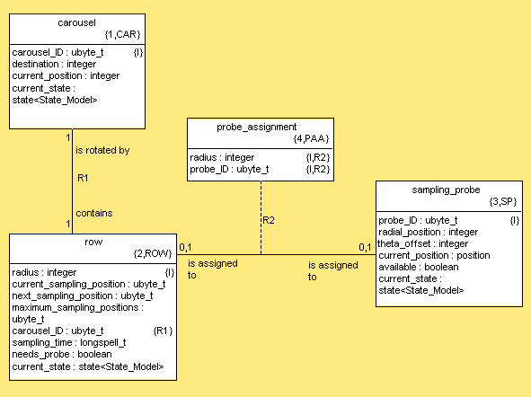
Figure 8.2. Autosampler Init Function
create object instance car of CAR;
car.carousel_ID=10;
car.current_position=10;
create object instance row of ROW;
relate row to car across R1;
row.radius=10;
row.current_sampling_position=0;
row.maximum_sampling_positions=20;
row.sampling_time=3000000;  // 3 seconds
row.needs_probe=false;
create object instance probe of SP;
probe.probe_ID=1;
probe.radial_position=20;
probe.theta_offset=40;
probe.current_position="up";
probe.available = true;
In systems with more than one domain, dynamic init is only slightly more complex. Initialization functions are written for each domain. These multiple init functions establish the preexisting instances (PEIs) for the multiple domains. The init functions are each marked with TagInitializationFunction in each domain's corresponding object.clr marking file.
In some systems it is important that certain domains be initialized before other domains. Or, there may be requirements on the ordering of the initialization between domains. In these cases, a function in only one domain is tagged as an init function (using TagInitializationFunction). This function then invokes functions in the other domains, thus imposing the desired order on the initialization sequence.
As an alternative to dynamic initialization, constant initialization allows for optimizing the space and speed required for system init.
Constant initialization involves providing the preexisting instances (PEIs) in the form of constant data. Instead of executing action language statements to create, relate and set attributes of preexisting instances, these PEIs are supplied as constant data already created, related and set.
ANSI C provides a construct called a static initializer. This construct allows constant data to be assigned to a variable at initialization time. MC-3020 provides a method for establishing the preexisting instances data in the form of ANSI C static intializers. The instance collections in the generated system are initialized with this data.
To obtain the PEI data necessary to provide constant initialization, a process must execute action language statements just as in dynamic initialization and then take a "snap shot" of the initialized data elements (PEIs) for use later. The PEI data from the snap shot is captured in an XML format. This PEI data is then used in placed of dynamic initialization action language.
Dynamic initialization as described in the section called “Dynamic Initialization” defines preexisting class instances and the associations between them by producing executable code from analysis model initialization function action language. The code produced in this fashion is executed once at system startup in order to establish any necessary preexisting instances. This mechanism may be unsatisfactory due to:
the execution time associated with the definition of preexisting instances and
the use of memory to hold code that is executed once (and only once) at system startup
MC-3020 addresses this issue in such a way as to provide an alternative approach for the establishing preexisting instances.
The model, with initialization functions is translated by MC-3020 for the development host with Model Debugger (MD) support, and the resulting MC-instrumented code is compiled and linked into an executable.
The instrumented executable built in step 1 is brought up on the development host under MD control, and an initialization function is executed. As the PEIs are created, the MD is notified, and it updates its view of the instance population.
After all the PEIs have been created (might require the execution of several initialization functions), the user instructs the MD to dump the instance population, and the MD does so, storing the instance population as an XML file.
The XML file created in step 3 is supplied to MC-3020 for a second translation, this time with tags indicating data defined preexisting instances. MC-3020 uses the XML file containing the PEI definitions to create initialized array definitions representing the PEIs. These arrays are prepopulated by ANSI C static initializers. It also translates the model for the target, ignoring the initialization that the user has now marked (with TagFunctionTranslationOff) so that code is not generated for them. The user then compiles and links the result into an executable that contains PEIs defined in data. The resulting executable does not contain executable code corresponding to the excluded initialization functions.
This approach, illustrated in Figure 8.3, “ Model Debugger Architecture” directly addresses both of the issues of speed and space identified in the introduction to this section.
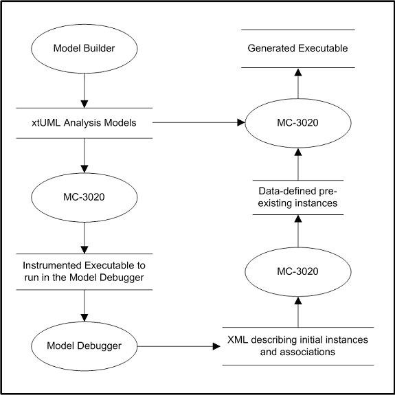
An XML data format has been defined which can represent instances, their associations and their attribute values. A file containing this XML data is generated. Then the constants of this file are supplied when generating the target system. Constant PEI initializers are created which establish PEIs just as if an init object had been executed.
Advantages to constant initialization include:
| memory space | Constant init saves instruction store space in the target system by generating more compact initialization in the form of preexisting instance array static initializers. |
| speed | Initialization is quicker with constant preexisting instances defined in data. |
Disadvantages to constant initialization include:
| complexity | The process for creating the initialization data for constant initialization is much more complex than for dynamic initialization. The model debugger is involved, and there are more steps. |
To use the preexisting instance support, an XML file containing the preexisting instance definitions needs to be supplied to the translation process. It is supplied into the (domain)/schema/sql directory. It is named (domain)_pei.xml.
Note that when the model is changed in any substantial way, the PEI data needs to be regenerated.
To create this file you must run the debugger, execute initialization code and save the results as XML. Two marks facilitate this. TagInitializationFunction marks function(s) to be executed during bring-up. This effectively replaces initialization objects. (Initialization objects are still supported, but discouraged.) Functions tagged to run at initialization bring-up can also be called during run time processing. Functions tagged for initialization are run in alphabetical order.
TagFunctionTranslationOff disables the translation of functions. This is convenient for enabling/disabling test cases. It is especially nice for PEI support. An init function can be tagged for running with model debugger. It can then be tagged off for the production compile using Preexisting Instances defined in data.
The general process is as follows:
Compile a model with debugging enabled.
Run with Nucleus BridgePoint Model Debugger and run initialization code.
Save the initialized data into XML file.
Recompile model incorporating the saved initialization XML from the debug session.
The specific details are as follows:
Compile a model with debugging enabled.
TagModelDebuggingOn to enable debugging and the transmission of XML state information to the Model Debugger. This marking function is invoked from the system.clr marking file.
Run the model compiler.
Run with Model Debugger and run the initialization code.
Launch Nucleus BridgePoint Model Debugger.
Run the compiled model (bin/rox.exe).
Invoke the domain function containing the initialization action language statements. Do this by right clicking on the function in the Model Debugger system browser. Select invoke function.
State or action step through the initialization code until all desired preexisting instances are created, related and initialized.
Save XML from model debugger.
Under the file menu of Model Debugger, save as... and save XML file into the (domain)/schema/sql directory as (domain)_pei.xml.
Exit Model Debugger.
Recompile model with preexisting instances defined in data.
Disable model debugging by not executing the TagModelDebuggingOn in the system.clr marking file.
Do not TagInitializationFunction in the domain.clr marking file for the initialization function that does creates, relates and inits. (You may want to run a function at bring-up for other purposes such as generating events.)
TagFunctionTranslationOff in the domain.clr marking file to prevent the initialization function from being translated into code that takes up time and space.
Mark on the constant initialization by invoking TagPEIsDefinedInData in the object.clr marking file.
make clean_all_src to erase generated source in domains.
make clean_sys_src to erase generated source in the system node.
If you copied files into system/user/source or system/user/include, you may need to change these not to include debug header files.
make all to rebuild the code with the preexisting instances defined in data and without debugging code.
If you are working with multiple domains, the process is the same with steps 2 and 3 repeated for each domain. Run the initialization of each domain separately. (Exit and restart Model Debugger for each domain.) Save separate XML files, one for each domain in its respective (domain)/schema/sql directory.
In the following example the pei test case (found in the pei directory in the MC-3020 installation) will be translated to use constant initialization. Figure 8.4, “PEI Test Case Class Diagram” shows the class diagram for this model.
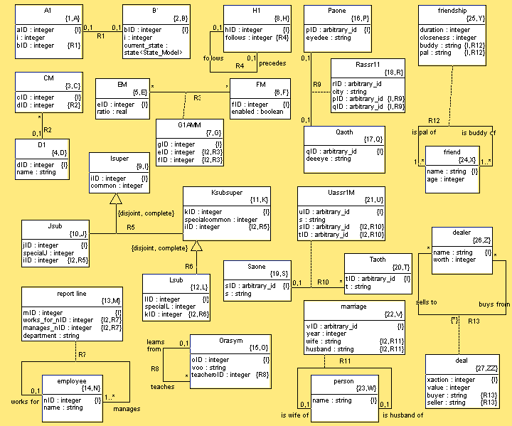
The model is designed to test various forms of associations between classes. Import the backup file, pei.sql, into your installation of Nucleus BridgePoint Model Builder as a model called pei. Check it in and create a configuration view. (Ensure all of the actions are parsed.)
Build a system node for the build (rox_init_node [dir]) and make the domain node (make dom_node domain=pei). Register the pei domain and the "LOG" realized domain by supplying the appropriate Register commands in registry.clr. Enable model debugging in system.clr. Wire the bridge between pei and LOG in bridge.clr, make the bridge skeleton files (make bridge_skel domain=pei ee=LOG) and copy the generated .c and .h files from the system/skel directory into the user/source and user/include directories. Build the executable as normal (make all).
Fire up Nucleus BridgePoint Model Debugger and run the generated executable (bin/rox.exe). Invoke the domain function "setup" from the system browser as shown in Figure 8.5, “MD System Browser for PEI Test Case”. (In Appendix E, PEI Test Case Setup the entire listing of the PEI test case is shown in detail.)
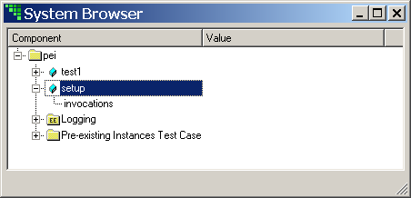
After invoking and stepping through the setup function, the Nucleus BridgePoint Model Debugger should show results as in Figure 8.6, “MD PEI Test Case Initializing”.
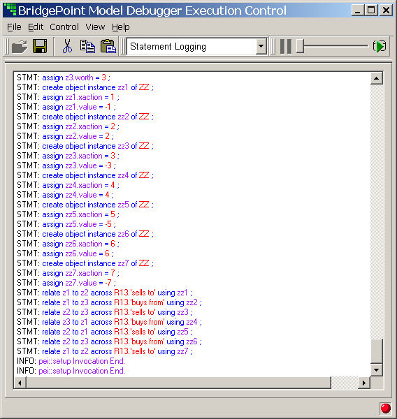
Save the session XML into schema/sql/pei_pei.xml under the system node created for this build.
Turn off model debugging in system.clr and block translation of the domain function "setup" (with
.invoke TagFunctionTranslationOff( "setup" )
in domain.clr). Clean out the source code generated with model debugging capability (make clean_all_src and make clean_sys_src). Activate the constant initialization capability by marking on the PEIs with
.invoke TagPEIsDefinedInData( "*", "*" )
in the object.clr marking file. By using the asterisks all available XML PEI data will be used.
Rebuild the application with the new marking (make all). The generated executable will be smaller and will start up faster because of the constant initialization.
To perform multiple domain constant initialization the user must collect XML data for each domain separately. A separate Nucleus BridgePoint Model Debugger session is started for each domain. The XML data is saved for each domain under the correct schema/sql directory. Below is a summary example using the autosampler example model (found in examples/ae of the MC-3020 installation).
In Figure 8.7, “Experiment Class Diagram” the experiment (exp) xtUML class diagram is shown. The autosampler class diagram is shown in Figure 8.1, “Autosampler Class Diagram”.
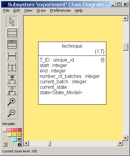
After the model is built with model debugging enabled, Nucleus BridgePoint Model Debugger and the generated executable (bin/rox.exe are started and the System Browser shows as in Figure 8.8, “MD System Browser for exp and as2”.
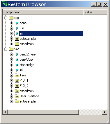
The initialization code is run for each domain separately. First, the autosampler domain function "init" is run as shown in Figure 8.9, “MD Initializing Autosampler”. The XML data is saved into as2/schema/sql/as2_pei.xml under the system node created for the build.
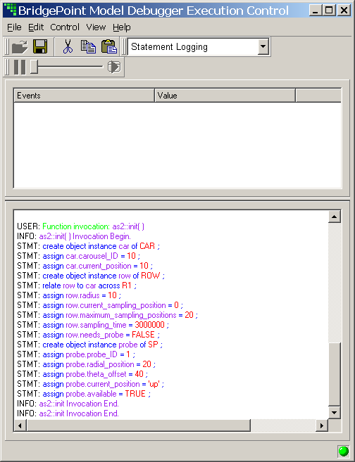
The Nucleus BridgePoint Model Debugger is exited and restarted (also restarting the generated application). The exp domain function "init" is run as shown in Figure 8.10, “MD Initializing Experiment”. The XML data is saved into exp/schema/sql/exp_pei.xml under the system node created for the build.
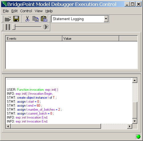
Turn off model debugging in system.clr and block translation of the domain functions "init" in both domains (with
.invoke TagFunctionTranslationOff( "init" )
in the domain.clr marking files). Clean out the source code generated with model debugging capability (make clean_all_src and make clean_sys_src). Activate the constant initialization capability by marking on the PEIs with
.invoke TagPEIsDefinedInData( "*", "*" )
in the object.clr marking files of both as2 and exp domains. Rebuild the application with the new marking (make all).
Following is an example of the gain (reduced code size) achieved by defining preexisting instances in data. Below are size measurements of a test case. The first case shows the output of the size command for a normal init-object-style generation (gcc/Cygwin). The second shows using PEIsDefinedInData.
To interpret the table:
text: code space
data: constants
bss: global and static variables
Table 8.1. PEI Comparison
| text | data | bss | dec | hex | filename |
|---|---|---|---|---|---|
| 27136 | 2560 | 11104 | 40800 | 9f60 | s2t/bin/rox.exe |
| 20992 | 10240 | 3744 | 34976 | 88a0 | s2s/bin/rox.exe |
This is a conservative test case. There are no state machines in the model. However there is procedural action language to access all of the instances either created or defined in data. The test case creates a total of 84 instances of 23 different objects with 39 links.
This simple test demonstrates a 15% reduction in code space and a significant speed-up in terms of initialization. Models with many preexisting instances will see very large reductions in code size.
Create, delete and link accessors are not generated unless actually needed. Early versions of MC-3020 were able to optimize out some delete and link accessors. Create accessors were generated unconditionally.
With the advent of preexisting instances defined in data it is possible for a system to have instances that were not created by action language in the system but were defined in data. As such, some classes may not need create accessors.
During first pass translation, MC-3020 identifies all creates, deletes, links and unlinks that are needed. All accessors are assumed to be not needed until action language is identified that uses the accessor. Only those accessors actually used in action language are generated.
With a static instance population composed totally of preexisting instances defined in data, it is possible to have a large number of instances that are rich with attributes and related with many other instances that have no create, delete, link or unlink accessors!
Lists are used by MC-3020 to keep track of collections of instances in the system. Collections of instances appear in several contexts including pools of instances of classes, sets of instances participating in an association and sets of instances resulting from SELECT MANY statements.
MC-3020 manages collections of instances using various collection mechanisms which are selectable through marking. As of version 3, MC-3020 provides two flavors of collection container, singly linked lists (slists) and doubly linked lists (dlists). Each container strategy has advantages and disadvantages with regard to code size and speed. In general, dlists are faster but take more storage. In the following sections details of these constructs are outlined.
Collections of class instances (objects) must be supported by any model compiler. Processing performs operations on these sets of data. Instances can be collected and organized in several ways. At minimum, a model compiler must be able to support:
selection from the existing instances of any specified class
selection from instances of any associated class
the analysis variable type inst_ref_set
We refer to the first case as instance extents. The second are referred to as association extents. The third are transient set variables (often called selection extents).
As of version 3, MC-3020 maintains collections in linked lists. Linked lists are flexible and relatively light weight (small, simple code).
Operations on sets include Insert, Remove, Clear, Copy, Cardinality, IsEmpty, Equality, Contains and Iterate. Some variations on these methods may also be included for various optimizations.
SELECT MANY makes a copy of an instance extent or association extent into a transient set variable. Cursors are used to iterate through sets of instances.
SELECT ANY returns the first element in the instance extent or association extent.
A set generates a different type of variable than does an element in a set. This allows for sets to have attributes such as a head (and perhaps a tail and cardinality). Set elements have attributes such as a link to the next element and a pointer to the substance of the data they contain.
Consistency between the three flavors of collections makes the model compiler simpler. Simpler usually means smaller code, but there are some exceptions to this general rule. Up through version 2.2 of MC-3020, instance extents, association extents and transient sets were treated almost identically. In versions above 2.2, instance extents get special treatment so that the model compiler can optimize for size and speed based upon characteristics true only of instance extents.
Instance extent sets are treated special in that their containers are never returned to the free pool and remain permanently attached to the instance data. Since the instances basically move between active (animate) and inactive (inanimate) lists, there is no need to detach the container as in association extents and transient set variables. Although this breaks the symmetry, it enables the generation of smaller and faster code.
MC-3020 applies these specializations as marking options to enhance the set operation performance of the model compiler generated code.
Singly linked lists are simple and small. For most of the set operations, singly linked lists are fast because of their simplicity. The exception to this is the delete operation. A delete operation on a singly linked set requires the address of the container of the data element being deleted. Delete also requires the address of the container preceding the deleted data and the address of the container following the deleted item. As input we have none of these three addresses but only the address of the data (object) being deleted.
In MC-3020 marked with slist containers, this meant that a search for the data element is required. This search begins at the head of the list and proceeds down the list until the data element is found. Variables track the current node and previous nodes as the list is traversed. Once the data element is found, these node variables contain 2 of the 3 three needed container addresses. A simple dereference of current->next yields the final container address. The singly linked list delete links the previous container to the next container thus unlinking the current node.
As collections get large, this linear search involved in set item deletion gets burdensome.
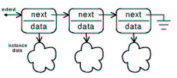
Adding a more capable container node structure alleviates the delete instance problem. With a prev pointer together with the next pointer, it is an easy matter to learn the address of the previous and following containers given the address of the container containing the data to be deleted. Note however, that we are not given the address of the container but the address of the data itself. Thus, unless a clever mechanism exists for deriving (divining) the container from the data handle, we are relegated to linear searches once again.
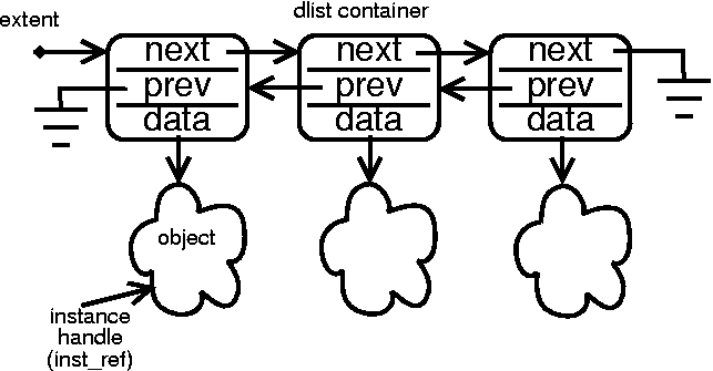
If data allocation of instances and containers is performed in a special way, there does exist a mechanism for deriving the address of the container from the address of the data.
In MC-3020 versions beyond 2.2, a doubly linked list container is available. Instances and containers are allocated in memory in a way that relates the instances to their containers mathematically. One container pool is allocated for each pool of class instances. These are parallel arrays. Remember that the container stays attached to the instance for the duration of system run time, since instances from the extents are simply moved from inactive to active and back for create and delete respectively.
During initialization, containers are linked to instance data in parallel. Container 0 is the container for instance index 0 of any particular class. Container 1 is the container for the instance at index two in the class pool array for this class. In other words, the array indexes for the containers are the same as the array indexes of the instances for which they serve.
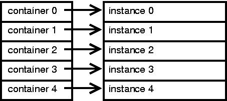
Thus, if we know the index of an instance data element, we know the index of the instance extent container pointing to it. We can derive the index of any pointer to an array element through pointer arithmetic.
index = pointer_to_array_element - address_of( array_element[0] )
We now have all the information needed to derive the address of an instance container, its previous container and next container all in constant time. The delete operation on an instance no longer involves a linear search of the extent.
Note that this "magic" only applies to sets managing instance extents. Deletions from association extents, UNRELATES, are not helped and still involve a search of the set. UNRELATES from very large association extents (hundreds or thousands) can suffer from linear search overhead.
A comparison of the two collection mechanisms in light of deleting instances shows the power of the constant time address derivation. Once instance extents grow larger than one hundred, the doubly linked collection mechanism with address derivation begins to show benefit. At extent sizes of ten thousand (10,000), the singly linked collection mechanism becomes two orders of magnitude slower than the doubly linked counterpart.
Another clever way to relate the instance containers to the instances themselves is to allocate them inside of the instances themselves. Under such a scheme, the base instance class would have the container class as its first element. This would amount to overloading the class with container members as data elements, namely next, prev, and object. Such a scheme renders trivial the mathematics of deriving the address of the instance from the address of the container. They are exactly the same. The address of the container is the address of the instance (and vice versa).
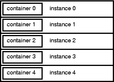
Such a scheme suffers a weakness in light of preexisting instance (PEI) support. The merged containers scheme adds two or three pointer size data elements to every class instance. To populate the instances with data, it would be necessary to populate the container pointers with the instances. Even if zero, this would mean 4 to 12 bytes of additional constant initializer data per instance in the system.
In light of this weakness, MC-3020 has opted for the parallel array approach to mathematically relating the containers to the instances. Even though MC-3020 does not (currently) use merged containers, there remains a great deal of merit in the approach.
As of version 3.1 MC-3020 supports debugging with the Nucleus BridgePoint Model Debugger. This adds powerful capabilities to the software developer.
Using XML data exchange and embedded tooling code generated by the model compiler, MC-3020 delivers real-time debugging of translated models.
The Model Debugger architecture, as originally conceived, is composed of four primary components: the Model Debugger itself, a host monitor, a target monitor, and an executable image generated from the model to be debugged. The host and target monitors, are separate entities with well-defined functionality. From a conceptual perspective, these four components can be allocated to completely separate processes or processors if it should prove beneficial to do so. Conversely, they can all be placed on the same processor. The Model Debugger will always runs as a separate process. These four components and the form of interaction between them are depicted in Figure 10.1, “ Model Debugger Architecture”.
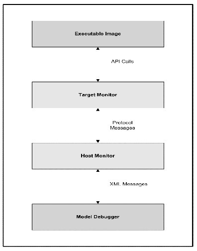
In version 3.1, MC-3020 implements this architecture as shown in Figure 10.2, “ Current Debugger/Compiler Interface”. This provides full code generation and debug capability, but restricted to the host development platform or to a TCP/IP socket-capable target.

Note that the host and target monitors are not only combined, but are incorporated into the executable image. As such, these three components exist as a single process that communicates with the Model Debugger process via XML messages across TCP/IP sockets. Both the Executable Image and Model Debugger processes run on the same host machine.
An interest in debugging models in a target environment using a Model Debugger compatible version of MC-3020 currently exists. In order to field such a capability in the first release, it was required to bundle host and target monitor capabilities with the executable image and communicate with the Model Debugger using XML Messages as shown in Figure 10.2, “ Current Debugger/Compiler Interface”. This assumes that the target is a socket-capable platform with sufficient RAM to run the tooled executable.
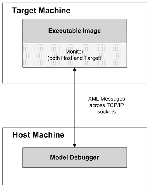
To run with Nucleus BridgePoint Model Debugger it is necessary to mark the system to generate the target monitor. This is accomplished with the marking function TagModelDebugginOn. See the section called “Marking On Model Debugger” for more details on this marking.
Before running the application with the debugger, an XML extraction of the model must be prepared. Use the command make gen_all_xml to create XML extractions for each domain in the system. If you do not prepare this XML file, Nucleus BridgePoint Model Debugger will detect an error and may exit with a fatal error.
When running with the target monitor enabled, additional code is translated into the generated code. There is code to communicate with the Model Debugger through a socket interface. There is an XML parser which parses the XML messages received from the debugger. In line with normal action processing are calls to debug processing which keeps the Model Debugger synchronized with the state of the generated target code.
With the addition of debugging with Nucleus BridgePoint Model Debugger another touch point between plain ASCII character sets and Unicode character sets is exposed. During a debug-enabled translation, the model compiler accesses and embeds various constructs from within the Nucleus BridgePoint xtUML model into the generated code. The constructs include the names and values of xtUML modeling elements. Many of these elements can be encoded in international character sets (for example Shift_JIS).
This chapter describes persistence services for MC-3020. The persistence support in MC-3020 allows instances of classes marked as persistent to survive across power cycles.
Persistence capability in a model compiler refers to the ability of the model compiler to allow dynamic data to persist across the boundary of a power cycle. The value of a persistent attribute written before power disconnect or power loss will be restored when the power returns.
MC-3020 does not support persistence of dynamic data in versions 3.3 and earlier. This section outlines requirements and operation of persistence support.
There are a great number of options for non-volatile storage (NVS) technologies in the embedded control world. Applications exist which use more than one non-volatile storage technology within the same system. It is required that modularity exist at the interface between general persistence services and the driver level code storing and retrieving data from non-volatile storage. A bridge is defined to allow MC-3020 users to build or replace this driver layer.
An option must be supplied to allow for the persisting of the current state of a persistent class instance or to use the default initial state. By default MC-3020 must restore the current state of instances. But the user must have a way of causing the current state to be the default current state that would normally be established for non-persistent class instances.
Different applications need to persist different amounts of data. The ability to persist at the class and domain levels allows for both large and small amounts of persistent data. MC-3020 supports persistence at class, subsystem and domain levels.
Persistence services for MC-3020 are light weight and flexible in terms of non-volatile storage technology. The persistence services are broken between two domains, PERSIST and NVS.
The PERSIST domain performs the commit and restore operations which commit instances to non-volatile storage and restore instances from non-volatile storage respectively. The PERSIST domain keeps track of which instances have been persisted, which links have been persisted and manages keeping the links synchronized with the instances during the power-up system initialization.
The NVS domain supplies a rudimentary but functionally complete persistent data storage and retrieval interface. The interface has characteristics of both a database and of a file system. The interface is rich enough to provide flexibility in the application of different non-volatile storage technologies.
MC-3020 persistence does not specify or depend upon a specific persistent storage technology. Therefore, only a standard interface (bridge) is defined. The user may deploy whatever available technology desired behind the bridge to the NVS domain. A sample implementation is supplied (in a file called sys_nvs.c/h) for use as the developer desires.
The domain chart below shows the bridge operations made visible to the application. commit is the primary function used by the application.
The architecture domain (MC-3020) automatically performs the inserts, updates and deletes to shuffle instance data between the RAM based collections of the application and the non-volatile persistent storage. Additionally, MC-3020 automatically performs the restore operation at power-up time.
Other domain interfaces are exposed and may be used at the discretion of the analyst.
A manual commit occurs when the user forces a commit of instance and link data to non-volatile store by synchronously invoking a PERSIST domain function (e.g. PERSIST::commit()). An automatic commit occurs when a commit is initiated by the software architecture "behind the scenes" based on pre-defined policy.
MC-3020 supports manual commit operations and performs automatic commits when necessary. Such automatic commits occur when instance and link delete operations are required.
When persistence and tasking are both enabled in the generated system, MC-3020 performs all commits automatically. It is not advised to manually commit in a multi-tasking system.
The implementation and deployment of the Non-Volatile Store (NVS) domain is the responsibility of the user. MC-3020 supplies one or more sample implementations of this domain to serve as design examples and source code "head starts". xtUML.org has collected additional samples over time and makes these available to users. However, with the variety of non-volatile storage technologies available and broadly differing platform requirements this deployment is left to the user for the purposes of flexibility.
Class instances and relationship instances (links) are stored in non-volatile storage. Their types are kept distinct from the rest of their instance data. In other words, the NVS domain distinguishes between instance data and link data.
Instances and links will be created and deleted in a rigorous fashion in the action language. Instances will be deleted only after all links have been "unrelated".
Only class instances and links between persistent classes are stored/retrieved from NVS. (Events and timers are not persisted.)
MC-3020 instance storage space is reused. The memory used to store the data for a class instance is moved from and to a "pool of elements" when creating and deleting class instances. Thus, after an instance is deleted, another instance may be created that uses the same physical storage. This poses a challenge when maintain two copies of this data (one in RAM and one in NVS).
If associations are not unlinked prior to the associated instances being deleted, links will be "orphaned" in non-volatile store. As such, this implementation of persistence requires the action language to carefully unlink before deleting.
See the section called “Marking Persistence” and the section called “Marking Persistence Cache Queue Depth” for explanation of the persistence marks.
A compiler flag exists to change the default behavior of the generated code with regard to restoring the current_state of persistence class instances. To turn off this behavior and therefore have the default initial state, compile with -DMC3020_DEFAULT_STATE.
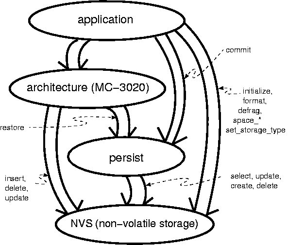
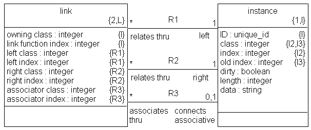
The commit function is called to indicate to the domain that the application wants to commit instances of classes and associations to non-volatile storage. This in turn causes NVS::insert to be called flushing to NVS elements from a list of instances and links that were queued when modified.
A return value of 0 indicates success.
integer commit(void);
The restore function is called by the architecture during bring-up after a power cycle. The restore function causes the classes contained in non-volatile storage to be read from store and written to the instance collection list.
A return value of 0 indicates success.
integer restore(integer class);
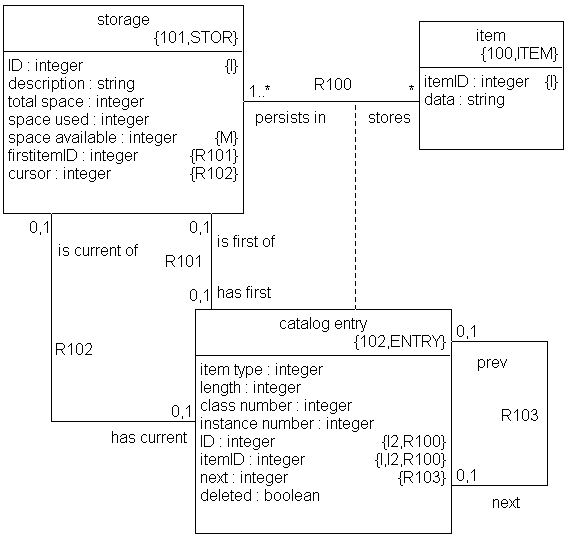
Many NVS domain functions return an integer return code. The values that the return code can take are outlined in the following listing:
#define NVS_RETURN_SUCCESS    0 /* All is well.                    */
#define NVS_ERROR_BAD_OPEN   -1 /* Could not open file.            */
#define NVS_ERROR_ITEM_LONG  -2 /* Data item is too long.          */
#define NVS_ERROR_BAD_SEEK   -3 /* Could not seek correctly.       */
#define NVS_ERROR_BAD_WRITE  -4 /* File did not write correctly.   */
#define NVS_ERROR_NOT_FOUND  -5 /* Did not find searched record.   */
#define NVS_ERROR_BAD_READ   -6 /* Read incorrect length of data.  */
#define NVS_ERROR_NO_ROOM    -7 /* Not enough room for insert.     */
#define NVS_ERROR_LENGTH     -8 /* Length not correct.             */
This can be found in the generated NVS_bridge.h file. A positive value is used to indicate the length of a buffer.
Function checksum provides a mathematical redundancy check on the integrity of the contents of the non-volatile store (NVS). This mathematical algorithm and the capabilities of the function are supplied by the implementor of the internals of the NVS module.
checksum provides an integer return code representing an integrity check on the contents of the NVS.
integer checksum(integer first, integer second);
The defrag function coalesces deleted records together and written records together. This allows for small fragments of free storage to be collected into a single contiguous free piece of storage. This function will typically take significant time to run. This time is a function of the specific non-volatile storage technology.
defrag provides an integer return code as listed above.
integer defrag(void);
delete searches the store for an item matching the input and deletes it. Deleted items cannot be retrieved from NVS in future invocations of select or search. delete chooses the item to erase based on two combinations of input arguments. If the delete is called with a key and a type, then the item in the NVS matching these key and type arguments is erased. Otherwise, if non-null data is given, the data and type arguments are used to identify the item to delete. When found, the item is marked as deleted and will not be readable from the store.
delete provides an integer return code as listed above.
integer delete(integer key, integer length, string pointer, integer type);
The format function erases the non-volatile store (NVS). It is only to be called when it is desired that a new NVS be cleared and prepared for writing for the first time.
integer format(void);
The initialize function resets the internal counters of the non-volatile store. (Note that these internal counters are the responsibility of the implementor of the internal of NVS and can contain information about the amount of data being used, etc.) No application/user data is written or changed in the store. This function is called automatically at power-up to prepare the store for access.
initialize provides an integer return code as listed above.
integer initialize(void);
The insert function adds items to the store. There are four input arguments. The first, key is the lookup key to the item. In the case of instance data, this key is a unique identifier for the item being inserted (added to the store). length is an integer representation of the length of the data byte sequence pointed to by pointer. type is the class type (instance or link) in integer form. The data pointed to by pointer is not modified. If the record being inserted already exists in the non-volatile store, the existing record will be updated. A return code provides status on the insert.
integer insert(integer key, integer length, string pointer, integer type);
next provides a way to cycle through reading each item from the store one at a time. This function returns the item currently being pointed to by the cursor (maintained inside the store). The buffer space available on the calling side is passed in as the length argument. If sufficient space is available in the buffer, the next item data will be copied into the given buffer pointed to by pointer. The length of the written data is returned as the return value. Also returned are the values of the key and type. The initialize function resets the internal cursor to the first item in the store.
integer next(integer * key, integer length, integer * pointer, integer * type);
The select function searches the store for a specific item with a key and type matching those given as input arguments. If a record is found that matches, it is copied into the data buffer pointed to by pointer. The length argument provides the amount of buffer space available on the calling side. The actual length of the returned record (if one is returned) is provided in the return value. The data behind the pointer argument is modified with the data found in the non-volatile store.
integer select(integer key, integer length, string * pointer, integer type);
The space_available function returns an integer representing the number of bytes not being used in the store. This number of bytes will actually hold fewer bytes due to the overhead of item meta-data (key, type, etc).
integer space_available(void);
The space_total function returns the overall size in bytes of the non-volatile store.
integer space_total(void);
The space_used function returns the number of bytes currently written in the store.
integer space_used(void);
The update function searches for a record in the store the same way that select does. When (and if) a record is found, the new data of length length pointed to by pointer is written into the store over the existing item. Since insert will perform an update when a record exists, it is more often used than update. No arguments are modified calling this function.
update provides an integer return code as listed above.
integer update(integer key, integer length, string pointer, integer type);
Function version provides an integer return value indicating the version of the data and/or format of the non-volatile store (NVS). This versioning algorithm and the capabilities of the function are supplied by the implementor of the internals of the NVS module. Two input arguments are used to provide flexible utility.
version provides an integer return code representing the version of the NVS (contents).
integer version(integer first, integer second);
Primary infrastructure changes involve the centralization of the create, delete and initialization of class instances. The following paragraphs explain this change and its design. A description of the implementation of the generated code follows with an explanation of the effects on speed, space and execution.
MC-3020 3.3 and before has a class-based create, delete, init design. The generated code contains a create accessor, delete accessor and factory initializer for each class in the modeled system. When an instance needs to be created, a routine specific to the class is invoked to allocate the implementation memory for the class instance. The attributes for the class instance are given reasonable default initial values. Identifying attributes of type unique_id are initialized to values certain to be unique with the generated system. The initial state of the new instance state machine is set.
In MC-3020 3.3 and before, when an instance needs to be deleted, a routine specific to the class is called to deallocate the implementation memory for the instance and perform needed clean-up.
MC-3020 3.3 generates "object factory initialization" routines. There is one of these methods for each class in the modeled domains. These methods are called exactly once at bring-up time to initialize the instance memory data pool for the collection of instances for the class. This routine took into consideration the fact that some of the instances in a collection may be allocated and initialized statically as preexisting instances.
The class-based create/delete/init approach is very flexible. It allows the model compiler designer the liberty of considering only the class in hand when generating the code. Different profiles of deployment code can be generated based upon the type of class (passive, active, associative, having preexisting instances, etc). However, having the create, delete and init accessor dispersed to every class is troublesome when considering a persistent restore operation from centralized non-volatile storage (NVS).
MC-3020 3.4 and beyond centralizes the create, delete and initialize operations. This is accomplished by moving the intelligence of the class-based create/delete/init procedures into a class-based data structure. This class_info array contains information about each class such that centralized operations can intelligently create, delete and initialize classes and instances.
The information contained in the class_info structure includes:
| active | The head of the list of active instances is used to collect the active instances together. |
| inactive | The head of the list of inactive instances is also maintained and used during create and delete operations. |
| container | Container refers to the head of the list of container elements used to maintain collections. The base of this list is used to calculate indexes into the array of instances. |
| pool | The base of the array representing the pool of instance data is accessible from the class_info array. The base of this list also is used to calculate indexes into the array of instances. |
| size | The size of the class (in bytes) is necessary for initialization and for persistence support. |
| initial_state | For active classes, the starting state of state machines must be kept for initialization of newly created active instances. |
| population | Population is the number of instances in the instance collection. |
| [preexisting instances] | Is used when there are preexisting instances defined in data. This element will inform the global initialization routine how many active instances to expect at power up so that initialization of collections may proceed accordingly. |
With the above information, it is possible to have centrally defined create, delete and initialization routines. These central routines rely on class-specific information from the class_info array rather than on class-specific generated procedures.
The persistence restore operation relies heavily upon the centralized create and initialization routines. Assuming for a moment a system that has no preexisting instances defined in data, a system having persistent classes must restore the class instance data from a central non-volatile storage unit (NVS).
When a system powers up, it performs the standard system level initialization to bring up event queues and timer support and other system level infrastructure. The system then initializes the collection mechanisms for all of the classes in the generated system. This involves linking the instance storage into lists (singly or doubly linked).
At this point in a non-persistence supporting system the initialization functions would be invoked to allow application level user initialization to occur. In a persistence supporting system, persistent class instances are restored from non-volatile storage before the user initialization functions are run.
The process of restoring class instances involves invoking the central create routine and populating the newly created instance with data from NVS. The data in the NVS needs to be rich enough such that the create routine knows which type of class to create. Once the type is communicated, the class_info array provides the necessary details to enable the correct instantiation of the new instance.
In MC-3020 3.3 the files *_object.c contain methods to create, delete and perform factory initialization of class instances. To compare implementations, view one of these files in 3.3 generated code.
In MC-3020 3.4 and beyond, these routines are centralized. The class_info structure is simply an array of pointers to elements of the structure which reside in the individual *_class.c files.
Each domain is assigned a unique number, and each class within a domain is assigned a unique number. An array of class_info arrays exists for the system containing information for all classes in all domains. During translation a domain-unique number is assigned to each class. This number serves as an index into the class_info array thus allowing centralized create, delete, init and other routines to look up statistics on any class in the modeled system.
Centralizing the create, delete and init functions has the intended effect of enabling a persistent restore operation that can rely on these class-independent routines (namely create). There are positive side-effects of this centralization.
Code space savings is the primary positive side effect. Instead of three routines for each class, there are now three routines for the entire system. This saves substantially on code size in the generated system. This effect will be greatest on systems with a large number of classes.
Other positive side effects include greater flexibility in features such as persistence.
Persistence services have cost in terms of execution speed, instruction store space, data memory and non-volatile storage space. This section enumerates those costs in as detailed a manner as practical.
To manage the bookkeeping of persistent instances, additional data is maintained. The following additional storage is used for each instance of each class.
The instance index is kept for each instance (all instances in the system). This value represents the index into the array of instances. The value is the index of the class instance when it was stored into NVS. This is required during the restore operation.
The class number is required inside the non-volatile store.
list of pointers to link functions
list of class numbers
NVS domain: approximated 3000 bytes (on 32 bit Intel)
PERSIST domain: approximated 4000 bytes (on 32 bit Intel)
There is significant cost in queueing the modified instances to the NVS cache queue.
MC-3020 supports running the xtUML application within multiple tasks or threads. The tasking uses the underlying OS/RTOS when one exists. MC-3020 can still run without an OS/RTOS, but if preemptive multi-tasking is desired in the application, it is available. The tasking/threading capabilities for MC-3020 are outlined here.
A well-modeled xtUML application is inherently concurrent. Actions from any two or more instances are considered to run simultaneously. This concurrency at the specification level simplifies the task of the developer. Smaller bits of system can be modeled to run somewhat independently. The life-cycles of classes in a system can be modeled mostly independently considering only their synchronization with other classes in the system. For example, the microwave door and the turntable run concurrently and mostly without recognizing or caring that the other exists or is running. If Developer A is modeling the door, and Developer B is modeling the turntable, they can do their state modeling with loose coupling.
To begin using the tasking/threading capability right away, jump to the section called “Marking for Tasking”.
A form of the inherent concurrency of the xtUML model can easily be translated and realized in a single-tasking microcontroller target. In single-tasking mode, MC-3020 interleaves the state actions of multiple concurrent instances of executing classes.
A single-tasking deployment architecture achieves a level of concurrency in which state actions from actively running class instances are interleaved. Such a deployment design serves well for applications requiring concurrency at the granularity of a state action. It is light weight and fast.
However, if a finer grained concurrency is desired, it will be necessary to use a multi-tasking deployment system. In a multi-tasking deployment environment, state actions can run in concurrently executing tasks or threads. The number of currently executing actions can be equal to the number of executing tasks (instead of just one).
To use tasking/threading with MC-3020, the user must mark the feature enabled providing the "flavor" of tasking/threading provided by the underlying operating system (OS) or real-time operating system (RTOS). Use the marking described the section called “Enabling Multi-Tasking”.
Once the tasking/threading capability has been enabled, the priorities of the desired tasks must be established. Various operating systems (OSes) and real-time operating systems (RTOSes) use different symbology for setting priority. For example, Nucleus PLUS uses integer numbers between 0 and 255 to indicate the priority of a task. (0 is the highest priority; 255 is the lowest.) Use the marking function described in the section called “Establishing Multi-Task Priority” to set the priority of the tasks in the xtUML generated system.
Classes must be mapped to the tasks identified with the marking functions above. Use the marking function described in the section called “Mapping Classes to Tasks/Threads” to map classes to tasks.
The primary reason for tasking in an xtUML modeled system involves the deployment of prioritization in the generated code.
An xtUML model may be inherently concurrent, but it is not inherently prioritized.
Simple prioritization of execution of a translated xtUML model can be achieved without multi-tasking. Events can be prioritized to modify the sequencing of state actions. MC-3020 provides event prioritization.
In a single tasking environment, a state action cannot be preempted. Therefore, a single task deployment environment is limited by the duration of the longest state action. Without preemption, a higher priority action may need to wait the entire duration of a state action of lower priority processing. Sometimes this is not an issue.
However, in many embedded applications the limits of a single task cannot be tolerated. We must map the xtUML application onto a multi-tasking/multi-threading architecture. By doing so, it is possible to map processing to various tasks based upon the required priorities. Higher priority action processing can be designed to preempt lower priority actions. We can take control away from the lower priority action and context switch into the higher priority action running in a higher priority task.
There are many possible strategies for mapping the components of an xtUML application to tasks. Event-based strategies and strategies based upon sequences of actions have been implemented successfully. MC-3020 has supported event based prioritization since version 2. As of MC-3020 version 4, prioritization using tasks/threads is supported. The mapping of xtUML artifacts to these tasks/threads is by class. Groups of classes are mapped to the tasks/threads running in the generated system.
xtUML model marking is used to identify which classes are translated to run in which tasks in the deployment target. Each class is marked identifying the task in which its generated code runs. The priority of the action processing of the class is used to determine an appropriate task. Higher priority classes get mapped to higher priority tasks. This separation allows for the processing of higher priority classes to preempt the processesing of lower priority classes.
Classes with state charts requiring low latency response to application events are mapped to high priority. Classes with little or no requirement for quick response are mapped to lower priority RTOS tasks.
The number of tasks required by the application is largely driven by prioritization. Concurrency plays a part in determining the number of tasks needed. The mapping to tasks must be accomplished with a clear understanding of both the xtUML application and of the deployment target hardware and RTOS.
A simple starting point is to have one task for each required level of priority. Map all classes having the same priority to the same task. For example map classes with tight coupling to time sensitive hardware to high priority task(s). Map classes that do non-critical "background" types of processing to a low priority task. Map everything else to a normal priority task.
In an xtUML application concurrency is assumed unless purposefully sequenced. Access to data that is shared between various classes/actions/functions must be synchronized. A simple, single-tasking deployment target may hide synchronization issues. A multi-tasking environment will not hide these modeling defects and indeed may aggravate them. If an xtUML application has not been properly synchronized, a truly preemptive multi-tasking kernel can uncover the modeling deficiencies.
Note that it is wise to map classes with strong processing and data interaction (coupling) into the same task. An improper mapping of classes to tasks can increase the overhead of processing by introducing undue task switching.
MC-3020 interfaces to the tasking/threading capabilities of the underlying OS/RTOS through a single interface layer module. The interface module is generated into the generated source of the system node into a file called sys_thread.c.
The tasking/threading interface consists of six interfaces. One interface provides for initialization (InitializeThreading). Another interface provides for creating threads (thread_create). Two interfaces allow for the locking and unlocking of shared resources such as event and instance queues (mutex_lock/unlock). Two final interfaces allow for the class activities in a task to go "non-busy" using no cycles when there is no work to do (nonbusy_wait/wake) and to "wake up" when new work arrives.
The resources that are protected by the locking and unlocking interfaces include instance event queue, self event queue, collection element free list, non-busy lock, serialization lock, instance queues, timers and interleaved bridges.
Documentation is found in the docs directory of the installed model compiler. Directions presented by the installation program that differ from this manual supersede the instructions listed here. The installation program will always provide the most recent and timely installation information. The text in the on-line user guide at MC-3020 User Guide will be even more up to date.
Uninstall any previous version of MC-3020 before beginning the installation process. There is an exception to this. If the version of MC-3020 on your computer is between version 3.2.0 and 3.3.0, then do not unintall. In this case skip the uninstall step and install right over the top of your previous installation.
Note MC-3020 will need to be reinstalled after upgrading Nucleus BridgePoint. MC-3020 relies on components within Nucleus BridgePoint. This uninstall/reinstall must occur any time that Nucleus BridgePoint is altered substantially (e.g upgrade, change in location of model repository). ROX_* environment variables need to be set to point to the correct (new) locations. Specifically, the variables ROX_PT_HOME and ROX_PT_REPOSITORY_HOME need to link to the correct directories. These variables use the old 8.3 format names. DIR /X is the DOS command to see the underlying file and path names.
Note that MC-3020 may not install onto a system that does not have the appropriate licensing.
Follow these steps and the directions on the screen. Cygwin and MC-3020 will be installed as needed.
On XP/2000/NT, log in as administrator.
Uninstall the old version of MC-3020 (if you have not done so already).
Insert MC-3020 compact disk into the CD ROM drive of the development platform.
If necessary, select Program->Run under the Start button.
Run the Setup program (setup.exe) on the CD.
Follow the instructions.
Reboot.
Excellent shell, compiler and build environment toolkit technology exists in the freely available Cygwin. MC-3020 3.1+ has Cygwin (and ksh) support right on the CD. Installation is automatic.
If you already have Cygwin installed, the MC-3020 installation CD will detect it and not install Cygwin. However, you may need to upgrade your Cygwin installation to include packages such as make, perl and xsltproc if you do not have them.
Permissions issues with Cygwin can pose a problem. Once Cygwin is installed, executables may be configured to allow only the owner of the file to read them and execute them. By default, Nucleus BridgePoint is set such that only an administrator can run the repository_bin executables. Keep this in mind if you seem to be having difficulty getting some build steps to execute correctly. Access can be granted to the executables using the chmod command (in the bin directory in question type chmod ugo+rx *.exe).
The 3.1+ release CD of MC-3020 has automatic installation of Cygwin (with ksh). These instructions will serve to document where these files are expected to be.
Follow these steps and the directions on the screen.
Insert MC-3020 compact disk into the CD ROM drive of the development platform.
Ensure that CD is mounted as an ISO-9660 type file system.
Run the setup.ksh program on the CD.
Follow the instructions.
Establish environment variables as directed by the installation program.
Get MC-3020 up and running right ``out of the box''. Instructions are provided here to build a sample system. It is a simple matter to substitute a different model for the sample provided here.
Attention to the following instructions will ensure the most productive installation and evaluation.
First, install MC-3020. See Appendix A, Deployment for installation instructions.
MC-3020 comes with a script that will translate two domains and compile them automatically. On Windows, this will work with no modifications when using GNU gcc. (By changing only the generated Makefile.user, the source can be recompiled with Microsoft Visual C/C++.) On Sun, this will work with no modification when using GNU gcc.
This example uses a pair of xtUML domains to model a chemical sampling system. The autosampler example model is coupled with a domain called experiment.
Import as2.sql and exp.sql found in the directory $ROX_MC_ROOT_DIR/examples/ae/ in the MC-3020 installation. Create a configuration view. (When importing a model into Nucleus BridgePoint Model Builder, remember that all subsystems, including TIM, must be deleted before importing the .sql.)
Start up a shell (Cygwin bash).
Execute $ROX_MC_ROOT_DIR/examples/ae/aedemo.
If translating the autosampler example model provided, import as2.sql and exp.sql found at $ROX_MC_ROOT_DIR/examples/ae/*.sql in the MC-3020 installation. Create a configuration view. (When importing a model into Nucleus BridgePoint Model Builder, remember that all subsystems, including TIM, must be deleted before importing the sql.)
Start up a shell.
Execute $ROX_MC_BIN_DIR/rox_init_node to create an application node. Provide a directory name for the application node. Be sure to note any directions given as output from this command.
Create a domain node by changing directories into your application node (created above) and executing make dom_node domain=xxx where xxx is the name of the model repository in Nucleus BridgePoint Model Builder. If translating the autosampler model provided, the command will be make dom_node domain=as2 and make dom_node domain=exp
Edit the system and domain marking files. If translating the example autosampler model, copy bridge.clr, datatype.clr, registry.clr and system.clr from $ROX_MC_ROOT_DIR/examples/ae/ to (node)/system/color/. Copy as2_domain.clr and as2_event.clr from $ROX_MC_ROOT_DIR/examples/ae/ to (node)/as2/color. These are pre-edited marking files that register the domains, wire the bridges and identify initialization and bridge objects. Default system and domain parameters are established.
If necessary for other models, edit the marking files in the directory (node)/system/color and (node)/xxx/color. The model compiler provides reasonable defaults for all unmarked artifacts. However, the defaults do not include bridging and registration. See examples in $ROX_MC_ROOT_DIR/examples/ae/gendcode.
Register xtUML domains and realized domains in register.clr. This registration process provides a shorthand name for a domain. The name and repository of the model (or code) can change; the registration provides indirection between the models and the translated name space and version space.
To wire bridges across domains (including realized domains), edit bridges.clr.
Provide data type precision information in datatype.clr.
To specify collection sizes for extents, edit domain.clr. Tracing switches as well as other knobs and dials are specified in this file.
Constrain extent sizes by editing object.clr.
Generate the ANSI C bridge skeletons by invoking make bridge_skel domain=as2 ee=CARPIO and make bridge_skel domain=as2 ee=SPPIO and make bridge_skel domain=as2 ee=UI
Generate the ANSI C source code by executing make gen_all.
Copy (node)/system/skel/*.h to (node)/system/user/include.
Copy (node)/system/skel/*.c to (node)/system/user/source.
Copy sys_user_co.c from $ROX_MC_ROOT_DIR/examples/ae/ to (node)/system/user/source/.
Copy sys_user_co.h from $ROX_MC_ROOT_DIR/examples/ae/ to (node)/system/user/include/.
Frameworks for bridge and operation code is generated into these skeleton directories. Simply add your own bridge and operation source code where directed in the generated file.
Compile the C source code by executing make all.
The executable, rox.exe, will be at (node)/bin/rox.exe. Run it on the NT host and see the state trace and action language trace. For the autosampler, the run ends waiting for the carousel stepper motor (which does not exist) to move the carousel.
MC-3020 levies certain restrictions upon the analyst. These restrictions and advice for capitalizing upon MC-3020 features are provided.
Cannot number an event with 0.
Prioritization of polymorphic events is not supported.
No dynamic memory allocation. System storage space for all instances is pre-allocated at start-up. This implies marking the OIM to define the maximum number of instances needed for each object. Note that MC-3020 intelligently determines rational defaults for instance and event populations. Marking is used to dial these in tightly.
Some platforms have no real time clock. Therefore date and time are not available in standard Gregorian or Caesarian form.
State machines are optimized for speed rather than space.
Events across bridges are not allowed.
Navigations of composed relationship must explicitly use the ``real'' (non-composed) relationship formalizations.
When altering a relationship formalized by combined referential attributes, MC-3020 does not (currently) propagate effect to all relationships which are involved in the definition of the combined referentials. This differs from MC-201x behavior. In this case the analysis model must assume responsibility for propagating combined referential influence, which will be forward compatible.
Relationship conditionality is not enforced by the model compiler.
Actions may not leave identifying attributes inconsistent beyond the end of any action.
Blind selections following a create and in the same scope as the create may not see the newly created instance in the extent.
create object instance of keyletters (create with no return value) is allowed only when the identifier of object keyletters is of type unique_ID.
The implementation of string expressions is somewhat inelegant. Strings in expressions are limited to simple binary operations.
There is no support for ``N to N + 1'' release compatibility. Changes to a model result in changes in the code, including event numbers, state numbers, etc. The registration theme is introduced to pave the way for future N+1 release capability.
This appendix begins by providing a general overview of model compilers (sometimes referred to as the software architecture) followed by a brief description of the major components of MC-3020. Next, a more detailed look is taken at the two types of tasks found in the MC-3020 architecture and how they interact. Finally, the general operational nature of each task type is described. The intent is to provide the reader with a complete, high level view of the MC-3020 architecture, sufficient to provide a context for the rest of this manual.
This section provides a general overview of how model compilers fit into the Shlaer-Mellor method.
The Shlaer-Mellor approach to software development begins by partitioning the system into separate subject matters referred to as domains. Each domain is then analyzed using xtUML modeling and finally the system is implemented by translating the xtUML models into the chosen implementation technology (e.g. language, operating system, custom hardware) using the model compiler.
The software architecture is that domain which deals with the subject matter of designing and implementing the system. It abstracts the design and implementation patterns appropriate for the system and defines mapping rules between the xtUML models and these design and implementation patterns. This approach provides a uniform set of data, function, and control abstractions that are used system wide and forms the basis for translating the xtUML models based on an automation of the mapping rules.
A software architecture is made up of three main components: mechanisms, rule files (formerly archetypes) and marks. In addition, build and diagnostic components are provided to facilitate constructing and debugging the system. These components are described in the following subsections.
A mechanism is architecture functionality that is specified, designed, coded, and compiled to work with all xtUML models. It is not customized on an xtUML element boundary. Examples of mechanisms in an object-oriented ANSI C model compiler include code for managing circular queues and modules written to perform set manipulation in a generic fashion.
In some architectures, pre-compiled mechanisms are not necessary. All code is generated from rule files or included in uncompiled source form. This is true of MC-3020.
MC-3020 is purely ANSI C and generates code that can be compiled by any compiler compliant with the ANSI standard. The core model compiler now uses no libraries or system functions at all. Generated code is pure native C. All string manipulation library functions (memcpy, strcpy, strcat and related) used in previous versions have been eliminated. Native C functions have replaced these system calls. This has been accomplished in such a way that a user can redefine the functions with a small rule file change or macro definition.
This change makes it simpler and easier to integrate with compilers of various makes and models and manufacturers. In addition, some simpler compilers will link in an entire library of system functions when any single function is accessed from the library. Only stdio.h remains as exposure on this front.
stdio.h is included simply for convenience during debug (for printf, etc). All generated code is simple, native C. When integrating realized external entities and timer services (TIM), other system libraries will be necessary. However, the core xtUML generated code remains simple ANSI C.
A rule file is a combination of an implementation pattern and translation rules for filling out that pattern based upon specifics of the xtUML models. Thus a rule file is designed to be customized on an xtUML element boundary. An example of a rule file in an object-oriented ANSI C model compiler is the code pattern for a struct that will be used to represent xtUML classes along with the translation rules for populating that code pattern with such xtUML elements as object name, attribute name, and valid events for that object.
When there is more than one software architecture element into which an xtUML element can be translated, marks (formerly "colors") are used to indicate which translation to make. The name ``mark'' comes from the visualization of using a highlighter pen to mark each element that has a particular property. Marks are used to direct the translation to select one of two or more branches in the translation rules. It is through marking that design decisions are injected during the translation process.
An example of the type of design information that is specified through marking is the mapping of analysis data types into implementation (e.g., C) data types. Clearly, this is information that does not belong in either the xtUML models or the model compiler itself. Such information is maintained outside the model compiler and models in marking tables that are accessed during the translation process.
In addition to the three basic components of a model compiler, the mechanisms, rule files, and marks, there are also two tools which come with an architecture to facilitate the translating and building of the system and provide some diagnostic capabilities for debugging the system. These are:
build tools
diagnostic tools
Just as assembly language is translated into machine code, and a high level language is translated into assembly code (which is then translated into machine code), the xtUML models and their translation into a high level language can be viewed as the next evolutionary step in language development. The xtUML models now become the new ``programming language'' and the software architecture the new ``compiler''. This approach is referred to as model based translative development (MBTD).
Applying this analogy to the model compiler components, the mechanisms represent the run-time library that comes with a conventional compiler to provide the functions necessary to successfully execute the compiled code in the chosen implementation environment. Likewise, the rule files represent the translation program or compiler that actually translates the high level source code input to assembly code output.
Figure D.1, “ Model Compiler Analogy with Nucleus BridgePoint Tool Set” shows an overview of how the model compilation process works in the context of the Nucleus BridgePoint tool set. The xtUML models are read from the repository of the Nucleus BridgePoint Model Builder and the translation rule files are fed into the Nucleus BridgePoint Generator.
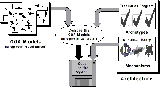
This section provides a brief overview of the MC-3020 architecture components by describing the Mechanisms, Archetypes, Marks, Build Tools, and Diagnostic Tools that make up the product.
The mechanisms for MC-3020 are implemented as ANSI C source code. This code compiles at build time to provide support for:
collections
xtUML timer interfaces
The Nucleus BridgePoint translation approach employs two different types of rule files, structural rule files and fragment generation rule files. Structural rule files produce the structure of the system (e.g. structure definitions, function definitions, state transition tables, etc.). Fragment generation rule files are used during the translation of the action language modeling the processing of the system.
MC-3020 provides the capability to direct the translation of the xtUML models by marking them to:
register xtUML and non-xtUML domains,
identify external entities as either xtUML or non-xtUML domains,
identify bridge objects for use by non-xtUML domains,
assign domain and system wide data type precisions,
tag initialization objects and objects to be excluded from translation,
establish limits to the extents of instance collections,
A detailed description of these capabilities is provided in Chapter 4, Marking
MC-3020 is shipped with a set of build tools implemented as shell scripts that can be used to translate models and compile and link the resulting code. These tools rely heavily on the make program. A detailed description of the build tools including instructions for their use is provided in Chapter 5, Translation and Build
After an application has been specified with Shlaer-Mellor xtUML models, MC-3020 provides the capability to translate those models into ANSI C source code. This source can be compiled, linked and located to produce an executable load image. This executable can be run on various targets. It can be converted into an Intel Hex format file or Motorola S-record format file for loading into an EPROM or flash memory.
Figure E.1. PEI Model Init Function
//
// Set up instances for existance test later on.
//
create object instance a of A;  // extras to see in PEIs
create object instance a of A;
create object instance a of A; a.i = 1;
create object instance b of B; b.i = 2;
relate a to b across R1;
create object instance a of A; a.i = 3;
create object instance b of B; b.i = 4;
relate b to a across R1;
create object instance a of A; a.i = 5;
create object instance b of B; b.i = 6;
relate a to b across R1;
create object instance b of B;  // extra to see it in PEIs

create object instance c1 of C; c1.cID = 1;
create object instance c2 of C; c2.cID = 2;
create object instance c3 of C; c3.cID = 3;
create object instance c4 of C; c4.cID = 4;
create object instance c5 of C;  // extra
create object instance d1 of D;  // extra
create object instance d2 of D; d2.name = "DeeTwo";
relate c1 to d2 across R2;
relate d2 to c2 across R2;
relate d2 to c3 across R2;
relate c4 to d2 across R2;

create object instance e1 of E; e1.eID = 1; e1.ratio = 0.314;
create object instance e0 of E; e1.eID = 100; e1.ratio = 0.1;
create object instance e2 of E; e2.eID = 2; e2.ratio = 2.718;
create object instance f3 of F; f3.fID = 3; f3.enabled = true;
create object instance f2 of F; f2.fID = 2; f2.enabled = false;
create object instance f1 of F; f1.fID = 1; f1.enabled = true;
create object instance g1 of G; g1.gID = 1;
create object instance g2 of G; g2.gID = 2;
create object instance g3 of G; g3.gID = 3;
create object instance g4 of G; g4.gID = 4;
relate e1 to f1 across R3 using g1;
relate f2 to e1 across R3 using g2;
relate f3 to e2 across R3 using g3;
relate e1 to f3 across R3 using g4;

create object instance h1 of H; h1.hID = 1;
create object instance h2 of H; h2.hID = 2;
create object instance h of H; h.hID = 99;  // extra to see in PEIs
create object instance h3 of H; h3.hID = 3;
create object instance h4 of H; h4.hID = 4;
relate h1 to h2 across R4.'precedes';
relate h2 to h3 across R4.'precedes';
relate h4 to h3 across R4.'follows';

create object instance i4 of I; i4.iID = 400; i4.common = 400;
create object instance i3 of I; i3.iID = 300; i3.common = 300;
create object instance i2 of I; i2.iID = 200; i2.common = 200;
create object instance i1 of I; i1.iID = 100; i1.common = 100;
create object instance j1 of J; j1.jID = 2; j1.specialJ = 2;
create object instance k1 of K; k1.kID = 11; k1.specialcommon = 11;
create object instance k2 of K; k2.kID = 22; k2.specialcommon = 22;
create object instance k3 of K; k3.kID = 33; k3.specialcommon = 33;
create object instance l2 of L; l2.lID = 222; l2.specialL = 222;
create object instance l3 of L; l3.lID = 333; l3.specialL = 333;
create object instance l1 of L; l1.lID = 111; l1.specialL = 111;
relate i1 to j1 across R5;
relate i2 to k3 across R5;
relate k2 to i3 across R5;
relate i4 to k1 across R5;
relate l1 to k1 across R6;
relate l3 to k2 across R6;
relate k3 to l2 across R6;

create object instance o1 of O; o1.oID = 1; o1.voo = "Kenny";
create object instance o2 of O; o2.oID = 2; o2.voo = "Cort";
create object instance o3 of O; o3.oID = 3; o3.voo = "Amy";
create object instance o4 of O; o4.oID = 4; o4.voo = "Ellen";
create object instance o5 of O; o5.oID = 5; o5.voo = "Brad";
relate o1 to o2 across R8.'teaches'; // Kenny teaches Cort.
relate o2 to o3 across R8.'teaches'; // Cort teaches Amy.
relate o4 to o2 across R8.'learns from'; // Ellen learns from Cort.
relate o5 to o2 across R8.'learns from'; // Brad learns from Cort.

create object instance n1 of N; n1.nID = 1; n1.name = "Pete";
create object instance n2 of N; n2.nID = 2; n2.name = "Dave";
create object instance n3 of N; n3.nID = 3; n3.name = "Alex";
create object instance n4 of N; n4.nID = 4; n4.name = "Jenn";
create object instance n5 of N; n5.nID = 5; n5.name = "Cale";
create object instance n6 of N; n6.nID = 6; n6.name = "Chris";
create object instance m1 of M; m1.mID = 1; m1.department = "SW";
create object instance m2 of M; m2.mID = 2; m2.department = "SW";
create object instance m3 of M; m3.mID = 3; m3.department = "HW";
create object instance m4 of M; m4.mID = 4; m4.department = "MEC";
create object instance m5 of M; m5.mID = 5; m5.department = "MEC";
relate n1 to n3 across R7.'manages' using m1;   // Pete manages Alex.
relate n1 to n4 across R7.'manages' using m2;   // Pete manages Jenn.
relate n5 to n2 across R7.'works for' using m3; // Cale works for Dave.
relate n1 to n6 across R7.'works for' using m4; // Pete works for Chris.
relate n6 to n2 across R7.'manages' using m5; // Chris manages Dave.

create object instance p1 of P; p1.eyedee = "Rox";
create object instance p2 of P; p2.eyedee = "Bita";
create object instance p3 of P; p3.eyedee = "Tina";
create object instance q1 of Q; q1.deeeye = "Shane";
create object instance q2 of Q; q2.deeeye = "Rusty";
create object instance q3 of Q; q3.deeeye = "Cort";
create object instance r1 of R; r1.city = "Indianapolis";
create object instance r2 of R; r2.city = "Lockport";
create object instance r3 of R; r3.city = "Battleground";
relate p1 to q3 across R9 using r1;
relate q2 to p2 across R9 using r3;
relate p3 to q1 across R9 using r2;

create object instance s1 of S; s1.s = "Rox";
create object instance s2 of S; s2.s = "Jacqui";
create object instance t1 of T; t1.t = "Clare";
create object instance t2 of T; t2.t = "Katrina";
create object instance t3 of T; t3.t = "Colleen";
create object instance t4 of T; t4.t = "Hannah";
create object instance t5 of T; t5.t = "Ruby";
create object instance u5 of U; u5.s = "Oct";
create object instance u4 of U; u4.s = "Aug";
create object instance u3 of U; u3.s = "Apr";
create object instance u2 of U; u2.s = "Dec";
create object instance u1 of U; u1.s = "Nov";
relate s1 to t4 across R10 using u2;
relate s1 to t5 across R10 using u1;
relate t1 to s2 across R10 using u5;
relate t2 to s2 across R10 using u4;
relate s2 to t3 across R10 using u3;

create object instance w1 of W; w1.name = "Cort";
create object instance w2 of W; w2.name = "Rox";
create object instance w3 of W; w3.name = "Sean";
create object instance w4 of W; w4.name = "Jacqui";
create object instance v1 of V; v1.year = 1988;
create object instance v2 of V; v2.year = 1990;
relate w1 to w2 across R11.'is husband of' using v1;
relate w4 to w3 across R11.'is wife of' using v2;

// friends and friendships
create object instance x1 of X; x1.name = "Cort"; x1.age = 39;
create object instance x2 of X; x2.name = "Rox"; x2.age = 38;
create object instance x3 of X; x3.name = "Sevina"; x3.age = 35;
create object instance x4 of X; x4.name = "Joe"; x4.age = 43;
create object instance x5 of X; x5.name = "Scott"; x5.age = 42;
create object instance x6 of X; x6.name = "Jason"; x6.age = 31;
create object instance y1 of Y; y1.duration = 1; y1.closeness = 10;
create object instance y2 of Y; y2.duration = 2; y2.closeness = 20;
create object instance y3 of Y; y3.duration = 3; y3.closeness = 30;
create object instance y4 of Y; y4.duration = 4; y4.closeness = 40;
create object instance y5 of Y; y5.duration = 5; y5.closeness = 50;
create object instance y6 of Y; y6.duration = 6; y6.closeness = 60;
create object instance y7 of Y; y7.duration = 7; y7.closeness = 70;
create object instance y8 of Y; y8.duration = 8; y8.closeness = 80;
create object instance y9 of Y; y9.duration = 9; y9.closeness = 90;
// Cort's friends
relate x1 to x2 across R12.'is buddy of' using y1;
relate x1 to x3 across R12.'is pal of' using y2;
relate x4 to x1 across R12.'is buddy of' using y3;
relate x5 to x1 across R12.'is pal of' using y4;
relate x1 to x6 across R12.'is buddy of' using y5;
// Rox's friends
relate x3 to x2 across R12.'is pal of' using y6;
// Joe's friends
relate x4 to x5 across R12.'is buddy of' using y7;
relate x4 to x6 across R12.'is pal of' using y8;
// Scott's friends
relate x6 to x5 across R12.'is buddy of' using y9;


// dealers and deals
create object instance z1 of Z; z1.name = "Joe"; z1.worth = 1;
create object instance z2 of Z; z2.name = "Pat"; z2.worth = 2;
create object instance z3 of Z; z3.name = "Jason"; z3.worth = 3;
create object instance zz1 of ZZ; zz1.xaction = 1; zz1.value = -1;
create object instance zz2 of ZZ; zz2.xaction = 2; zz2.value = 2;
create object instance zz3 of ZZ; zz3.xaction = 3; zz3.value = -3;
create object instance zz4 of ZZ; zz4.xaction = 4; zz4.value = 4;
create object instance zz5 of ZZ; zz5.xaction = 5; zz5.value = -5;
create object instance zz6 of ZZ; zz6.xaction = 6; zz6.value = 6;
create object instance zz7 of ZZ; zz7.xaction = 7; zz7.value = -7;
relate z1 to z2 across R13.'sells to' using zz1;
relate z1 to z3 across R13.'buys from' using zz2;
relate z2 to z3 across R13.'sells to' using zz3;
relate z3 to z1 across R13.'buys from' using zz4;
relate z2 to z1 across R13.'sells to' using zz5;
relate z2 to z3 across R13.'buys from' using zz6;
relate z1 to z2 across R13.'sells to' using zz7;
Reproduction or copying of "MC-3020 Model Compiler User's Guide" is prohibited except by express license agreement with Mentor Graphics Corporation.
Nucleus BridgePoint is a registered trademark of Mentor Graphics Corporation. Microsoft Windows is registered trademarks of Microsoft Corporation. Solaris is a trademark of Sun Microsystems, Inc.
Other products or services mentioned in this document are identified by the trademark, service marks, or products names as designated by the companies who market these products.
RESTRICTED RIGHTS LEGEND: Use, duplication, or disclosure by the Government is subject to restrictions as set forth in subparagraphs (c)(1)(ii) of the Rights in Technical Data and Computer Software clause at 252.227-7013 (48 CFR, Ch.2).
Manufacturer is: Mentor Graphics Corporation
Enhancements provided by:
| Radix Unlimited, USA. |
| TOYO Corporation, Japan. |
| Sony Corporation, Japan. |
| Project Technology Corporation, USA. |
| ROX Software, Inc., USA. |